

Price Match Guarantee

In-stock parts ship the same day

365-Day Return Policy
Price Match GuaranteeGET PRO PRICING
Video & Articles: Appliance & Equipment RepairWhirlpool Gas Dryer Gas Valve Burner Kit Replacement #W10823508 


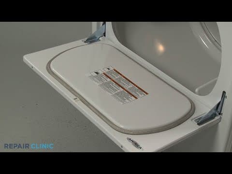
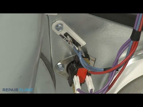
Whirlpool Gas Dryer Gas Valve Burner Kit Replacement #W10823508
Skill Level
Total Parts Cost
$181.53Estimated Savings
$112.5008:53
- Description
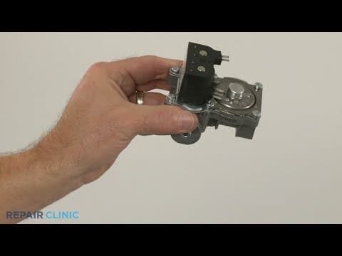
This video provides step-by-step repair instructions for replacing the gas valve burner kit on a Whirlpool gas dryer (model #WGD49STBW2). The most common reason for replacing the kit is if the burner will not light.
This kit replacement video is applicable to the following brands:
Whirlpool, Maytag
Don't forget to like and comment on this video and subscribe to our channel!
This kit replacement video is applicable to the following brands:
Whirlpool, Maytag
Don't forget to like and comment on this video and subscribe to our channel!
Step By Step Instructions
1
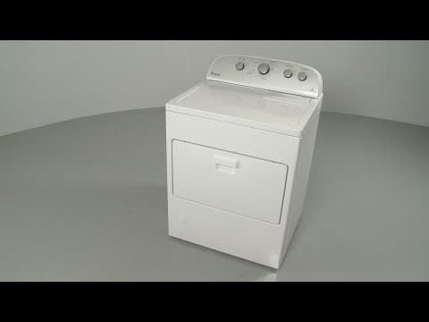
Whirlpool Gas Dryer - WGD49STBW2
2
Dryer Gas Valve & Burner Assembly Replacement
3
Tools needed: quarter-inch socket or nut driver, 5/16th inch socket or nut driver, Phillips-head screwdriver, putty knife
4
Shock Hazard
5
Be sure to unplug the power cord.
6
Fire Hazard
7
Shut off the gas supply.
8
Water Hazard
9
Shut off the cold water supply as well.
10
Remove the water inlet line from the steam valve ? be prepared for some water to spill.
11
Remove the external venting as well.
12
Use a quarter-inch socket or nut driver to unthread the screw to release the power cord access panel.
13
Unthread the remaining screws securing the rear panel.
14
Heavy
15
Pull the rear panel out and up to remove.
16
Now disconnect the gas supply line and remove the fitting.
17
Use a 5/16th inch socket or nut driver to unthread the two screws securing the gas inlet pipe bracket.
18
Now pull out the lint filter and place a towel over the opening to prevent the screws from falling into the venting.
19
Use a Phillips-head screwdriver to unthread the screws securing the main top to the lint filter housing.
20
Now insert a putty knife under the main top to release the two spring clips.
21
Sharp
22
Lift the main top up.
23
Disconnect the door switch wire connecter.
24
Use a 5/16th inch socket or nut driver to unthread the screws securing the front panel.
25
Heavy
26
Lift the front panel up and out to remove.
27
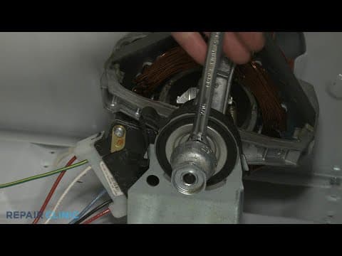
Now reach under the drum and push the idler pulley to release the tension on the belt then unthread the belt from the idler pulley and motor pulley.
28
You can use the belt to help lift out the drum.
29
Disconnect the two solenoid coil wire connecters.
30
Disconnect the igniter wire connecter and the flame sensor wires as well.
31
Next, unthread the two screws securing the front of the gas valve bracket to the dryer base.
32
Loosen the screw securing the middle of the bracket.
33
You can now slide the entire gas valve and burner assembly out.
34
Be aware ? if your dryer uses propane gas, you will need to transfer the orifice from the old gas valve to the new one.
35
You may have to transfer the cap as well?or rotate the dial to the appropriate setting for propane.
36
Fragile
37
Prepare the new gas valve and burner assembly for installation by aligning the new igniter on the bracket and securing it with the provided screw.
38
Be careful not to damage the filament.
39
Now slide the gas inlet pipe through the opening in the rear bulkhead as you align the burner assembly in the burner housing and the gas valve bracket on the base.
40
Tighten the middle screw to hold the bracket in place, then thread and tighten the two front screws.
41
Connect the flame sensor wires to the terminals.
42
Connect the igniter wire connecter.
43
Connect the wire connecters to the solenoid coils.
44
Confirm that the idler pulley is in place on the base, then replace the drum by aligning the rim with the felt seal on the rear rollers.
45
Loop the belt around the idler pulley and motor pulley in a zig-zag formation.
46
Now, rotate the drum to help align the belt.
47
Reinstall the front panel by aligning the front of the drum on the bulkhead while hooking the slots at the bottom of the panel on the mounting clips attached to the frame.
48
Replace the screws to secure the panel.
49
Reconnect the door switch wire.
50
Lower the main top and snap it into position.
51
Thread and tighten the screws to secure the main top to the lint filter housing.
52
Replace the lint filter.
53
Reposition the existing bracket to secure the gas inlet pipe and secure it with the screws.
54
Apply thread sealant to the threads of the gas inlet pipe, then attach the fitting.
55
Reconnect the gas line to the fitting.
56
Reinstall the rear panel by inserting the lower tabs behind the edge of the base.
57
Fully align the panel then thread and tighten all of the screws.
58
Replace the power cord access panel and secure it with the screw.
59
Reattach the water inlet line to the steam valve.
60
Reattach the external venting to the exhaust outlet.
61
Turn the gas supply back on and apply a soap and water solution to the connection to confirm there is no gas leak.
62
The solution will bubble if there is a leak.
63
Turn the cold water supply back on, plug the power cord back in and your dryer should be ready for use.
Description
This video provides step-by-step repair instructions for replacing the gas valve burner kit on a Whirlpool gas dryer (model #WGD49STBW2). The most common reason for replacing the kit is if the burner will not light.
This kit replacement video is applicable to the following brands:
Whirlpool, Maytag
Don't forget to like and comment on this video and subscribe to our channel!
This kit replacement video is applicable to the following brands:
Whirlpool, Maytag
Don't forget to like and comment on this video and subscribe to our channel!
Step-By-Step Instructions
1
Whirlpool Gas Dryer - WGD49STBW2
2
Dryer Gas Valve & Burner Assembly Replacement
3
Tools needed: quarter-inch socket or nut driver, 5/16th inch socket or nut driver, Phillips-head screwdriver, putty knife
4
Shock Hazard
5
Be sure to unplug the power cord.
6
Fire Hazard
7
Shut off the gas supply.
8
Water Hazard
9
Shut off the cold water supply as well.
10
Remove the water inlet line from the steam valve ? be prepared for some water to spill.
11
Remove the external venting as well.
12
Use a quarter-inch socket or nut driver to unthread the screw to release the power cord access panel.
13
Unthread the remaining screws securing the rear panel.
14
Heavy
15
Pull the rear panel out and up to remove.
16
Now disconnect the gas supply line and remove the fitting.
17
Use a 5/16th inch socket or nut driver to unthread the two screws securing the gas inlet pipe bracket.
18
Now pull out the lint filter and place a towel over the opening to prevent the screws from falling into the venting.
19
Use a Phillips-head screwdriver to unthread the screws securing the main top to the lint filter housing.
20
Now insert a putty knife under the main top to release the two spring clips.
21
Sharp
22
Lift the main top up.
23
Disconnect the door switch wire connecter.
24
Use a 5/16th inch socket or nut driver to unthread the screws securing the front panel.
25
Heavy
26
Lift the front panel up and out to remove.
27
Now reach under the drum and push the idler pulley to release the tension on the belt then unthread the belt from the idler pulley and motor pulley.
28
You can use the belt to help lift out the drum.
29
Disconnect the two solenoid coil wire connecters.
30
Disconnect the igniter wire connecter and the flame sensor wires as well.
31
Next, unthread the two screws securing the front of the gas valve bracket to the dryer base.
32
Loosen the screw securing the middle of the bracket.
33
You can now slide the entire gas valve and burner assembly out.
34
Be aware ? if your dryer uses propane gas, you will need to transfer the orifice from the old gas valve to the new one.
35
You may have to transfer the cap as well?or rotate the dial to the appropriate setting for propane.
36
Fragile
37
Prepare the new gas valve and burner assembly for installation by aligning the new igniter on the bracket and securing it with the provided screw.
38
Be careful not to damage the filament.
39
Now slide the gas inlet pipe through the opening in the rear bulkhead as you align the burner assembly in the burner housing and the gas valve bracket on the base.
40
Tighten the middle screw to hold the bracket in place, then thread and tighten the two front screws.
41
Connect the flame sensor wires to the terminals.
42
Connect the igniter wire connecter.
43
Connect the wire connecters to the solenoid coils.
44
Confirm that the idler pulley is in place on the base, then replace the drum by aligning the rim with the felt seal on the rear rollers.
45
Loop the belt around the idler pulley and motor pulley in a zig-zag formation.
46
Now, rotate the drum to help align the belt.
47
Reinstall the front panel by aligning the front of the drum on the bulkhead while hooking the slots at the bottom of the panel on the mounting clips attached to the frame.
48
Replace the screws to secure the panel.
49
Reconnect the door switch wire.
50
Lower the main top and snap it into position.
51
Thread and tighten the screws to secure the main top to the lint filter housing.
52
Replace the lint filter.
53
Reposition the existing bracket to secure the gas inlet pipe and secure it with the screws.
54
Apply thread sealant to the threads of the gas inlet pipe, then attach the fitting.
55
Reconnect the gas line to the fitting.
56
Reinstall the rear panel by inserting the lower tabs behind the edge of the base.
57
Fully align the panel then thread and tighten all of the screws.
58
Replace the power cord access panel and secure it with the screw.
59
Reattach the water inlet line to the steam valve.
60
Reattach the external venting to the exhaust outlet.
61
Turn the gas supply back on and apply a soap and water solution to the connection to confirm there is no gas leak.
62
The solution will bubble if there is a leak.
63
Turn the cold water supply back on, plug the power cord back in and your dryer should be ready for use.
Applicable Product Model
Parts Needed
Gas Valve Assembly
$181.53
Recommended Tools and Accessories
Conversion Kit
$58.42
Total$0.00
Related Articles & Videos




Our Story
Family-owned and operated since 1912, Burke America Parts Group is the longest-running genuine appliance, HVAC, and outdoor power equipment parts solution in North America. At Repair Clinic, we're proud to be an international brand trusted by the pros as well as the DIY community.
About Repair Clinic
© 2026 RepairClinic.com