

Price Match Guarantee

In-stock parts ship the same day

365-Day Return Policy
Price Match GuaranteeGET PRO PRICING
Video & Articles: Appliance & Equipment RepairToro Snowblower Governor Arm Replacement 21-0155
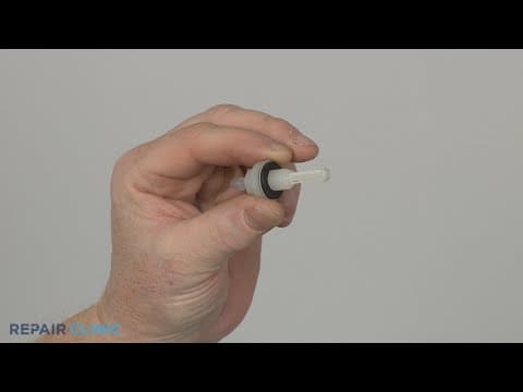
Toro Snowblower Governor Arm Replacement 21-0155
Skill Level
Total Parts Cost
$4.01Estimated Savings
$112.5009:11
- Description
This video provides step-by-step repair instructions for replacing the governor arm on a Toro snowblower.
All of the information for this video is applicable to the following brands:
Toro
All of the information for this video is applicable to the following brands:
Toro
Step By Step Instructions
1
Toro Snowblower - Model 38752
2
Snowblower Governor Arm Replacement
3
Tools Needed
4
You will need a 3/8th inch socket, a phillips-head screwdriver, an 8mm socket, a half-inch socket, a 10mm socket, a 10mm wrench and a small flat-head screwdriver for this procedure.
5
Hot
6
Make sure the engine has cooled.
7
Spill
8
Be sure to perform this procedure with no fuel in the tank.
9
Use a 3/8th inch socket to unthread the three mounting bolts securing the chute handle and the chute itself.
10
Remove the assembly and detach the handle.
11
Using a phillips-head screwdriver, unthread the screw to release the chute ring seal.
12
Unthread the two front housing mounting screws.
13
Unthread the three screws from the right side of the housing.
14
Use the 3/8th inch socket or nut driver to unthread the mounting bolt securing the housing to the rear bracket.
15
Unthread the screws to release the two retaining clamps holding the housing to the handle.
16
You can now fully remove the housing.
17
Use an 8mm socket to unthread the six bolts securing the muffler cover.
18
Use a half-inch socket to fully unthread the upper bolts securing the handle assembly.
19
Sharp
20
Lower the handle to fully remove the muffler cover.
21
Spill
22
Detach the primer hose from the carburetor ? be prepared for some fuel to spill.
23
Disconnect the wires from the key switch terminals.
24
Use a 10mm socket to unthread the nuts securing the control housing.
25
Pull the housing off of the mounting bolts.
26
Use a 10mm socket to unthread the two nuts and an 8mm socket to unthread the screw securing the side access cover.
27
Pull the cover off.
28
Use the 8mm socket to unthread the two mounting screws securing the trim and fuel tank.
29
Unthread the additional screw on the left securing the tank.
30
Spill
31
Release the clamp to detach the fuel hose and you can fully remove the tank.
32
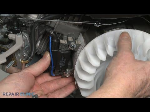
Note the locations of the governor spring, the throttle return spring, and the throttle rod, then detach them from the governor arm.
33
Using a 10mm wrench, loosen the nut and bolt securing the governor arm.
34
Note the orientation of the arm and the shaft, then use a small flat-head screwdriver to pry the end of the arm apart to remove it.
35
Install the new governor arm by aligning it on the shaft.
36
Slide the throttle return spring onto the throttle rod, then insert the appropriate ends of both the rod and the spring into the holes in the governor arm.
37
Connect the rod and spring to the appropriate holes in the carburetor throttle lever.
38
Hook the long end of the governor spring into the lower hole in the speed control lever and the short end into the appropriate hole in the governor arm.
39
To calibrate the arm, pull it back to open the carburetor to full throttle, then use pliers to rotate the governor shaft clockwise until it stops.
40
Tighten the nut and bolt to secure the arm.
41
Reinstall the fuel tank by first connecting the fuel hose to the port and securing the clamp.
42
Reposition the tank and thread the left-side screw.
43
Realign the trim and thread the screws.
44
Realign the side access cover and thread the screw and nuts to secure.
45
Reposition the control housing, then thread and tighten the mounting nuts.
46
Connect the wires to the key switch terminals.
47
Reattach the primer hose to the carburetor.
48
Reposition the muffler cover and thread the six bolts to secure.
49
Reposition the handle assembly and rethread the upper bolts.
50
Reposition the housing.
51
Align the two retaining clamps and thread the screws to secure the housing to the handle.
52
Rethread the mounting bolt to secure the housing to the rear bracket.
53
Replace the three right-side screws.
54
Rethread the two screws securing the front of the housing.
55
Reposition the ring seal on the housing so the phillips-head screw hole aligns with the appropriate screw hole in the gear ring, then thread the screw.
56
Realign the handle on the chute, then reposition the assembly on the ring seal and thread the three mounting bolts to secure.
57
Fill the tank with fuel.
58
Congrats! Your snowblower is ready for use.
Description
This video provides step-by-step repair instructions for replacing the governor arm on a Toro snowblower.
All of the information for this video is applicable to the following brands:
Toro
All of the information for this video is applicable to the following brands:
Toro
Step-By-Step Instructions
1
Toro Snowblower - Model 38752
2
Snowblower Governor Arm Replacement
3
Tools Needed
4
You will need a 3/8th inch socket, a phillips-head screwdriver, an 8mm socket, a half-inch socket, a 10mm socket, a 10mm wrench and a small flat-head screwdriver for this procedure.
5
Hot
6
Make sure the engine has cooled.
7
Spill
8
Be sure to perform this procedure with no fuel in the tank.
9
Use a 3/8th inch socket to unthread the three mounting bolts securing the chute handle and the chute itself.
10
Remove the assembly and detach the handle.
11
Using a phillips-head screwdriver, unthread the screw to release the chute ring seal.
12
Unthread the two front housing mounting screws.
13
Unthread the three screws from the right side of the housing.
14
Use the 3/8th inch socket or nut driver to unthread the mounting bolt securing the housing to the rear bracket.
15
Unthread the screws to release the two retaining clamps holding the housing to the handle.
16
You can now fully remove the housing.
17
Use an 8mm socket to unthread the six bolts securing the muffler cover.
18
Use a half-inch socket to fully unthread the upper bolts securing the handle assembly.
19
Sharp
20
Lower the handle to fully remove the muffler cover.
21
Spill
22
Detach the primer hose from the carburetor ? be prepared for some fuel to spill.
23
Disconnect the wires from the key switch terminals.
24
Use a 10mm socket to unthread the nuts securing the control housing.
25
Pull the housing off of the mounting bolts.
26
Use a 10mm socket to unthread the two nuts and an 8mm socket to unthread the screw securing the side access cover.
27
Pull the cover off.
28
Use the 8mm socket to unthread the two mounting screws securing the trim and fuel tank.
29
Unthread the additional screw on the left securing the tank.
30
Spill
31
Release the clamp to detach the fuel hose and you can fully remove the tank.
32
Note the locations of the governor spring, the throttle return spring, and the throttle rod, then detach them from the governor arm.
33
Using a 10mm wrench, loosen the nut and bolt securing the governor arm.
34
Note the orientation of the arm and the shaft, then use a small flat-head screwdriver to pry the end of the arm apart to remove it.
35
Install the new governor arm by aligning it on the shaft.
36
Slide the throttle return spring onto the throttle rod, then insert the appropriate ends of both the rod and the spring into the holes in the governor arm.
37
Connect the rod and spring to the appropriate holes in the carburetor throttle lever.
38
Hook the long end of the governor spring into the lower hole in the speed control lever and the short end into the appropriate hole in the governor arm.
39
To calibrate the arm, pull it back to open the carburetor to full throttle, then use pliers to rotate the governor shaft clockwise until it stops.
40
Tighten the nut and bolt to secure the arm.
41
Reinstall the fuel tank by first connecting the fuel hose to the port and securing the clamp.
42
Reposition the tank and thread the left-side screw.
43
Realign the trim and thread the screws.
44
Realign the side access cover and thread the screw and nuts to secure.
45
Reposition the control housing, then thread and tighten the mounting nuts.
46
Connect the wires to the key switch terminals.
47
Reattach the primer hose to the carburetor.
48
Reposition the muffler cover and thread the six bolts to secure.
49
Reposition the handle assembly and rethread the upper bolts.
50
Reposition the housing.
51
Align the two retaining clamps and thread the screws to secure the housing to the handle.
52
Rethread the mounting bolt to secure the housing to the rear bracket.
53
Replace the three right-side screws.
54
Rethread the two screws securing the front of the housing.
55
Reposition the ring seal on the housing so the phillips-head screw hole aligns with the appropriate screw hole in the gear ring, then thread the screw.
56
Realign the handle on the chute, then reposition the assembly on the ring seal and thread the three mounting bolts to secure.
57
Fill the tank with fuel.
58
Congrats! Your snowblower is ready for use.
Applicable Product Model

Related Articles & Videos




Our Story
Family-owned and operated since 1912, Burke America Parts Group is the longest-running genuine appliance, HVAC, and outdoor power equipment parts solution in North America. At Repair Clinic, we're proud to be an international brand trusted by the pros as well as the DIY community.
About Repair Clinic
© 2026 RepairClinic.com