

Price Match Guarantee

In-stock parts ship the same day

365-Day Return Policy
Price Match GuaranteeGET PRO PRICING
Video & Articles: Appliance & Equipment RepairFrigidaire Electric Laundry Center Thermal Limit Replacement (134120900) 

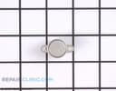
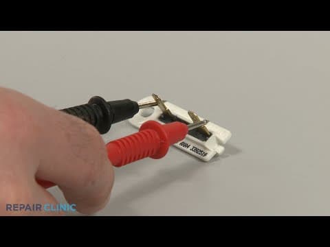
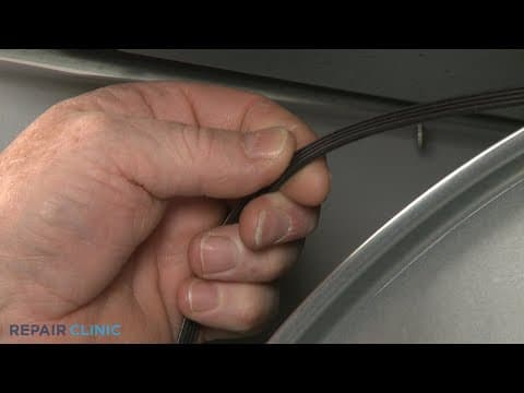
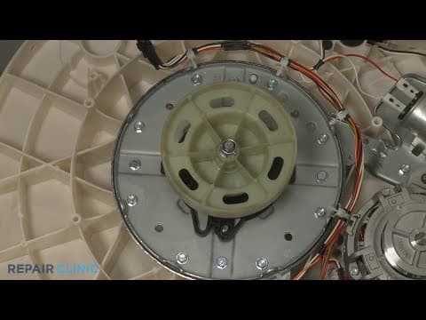
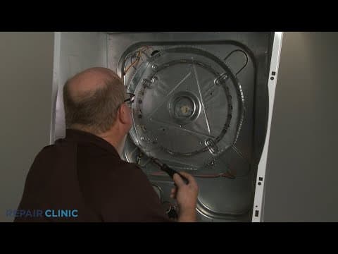
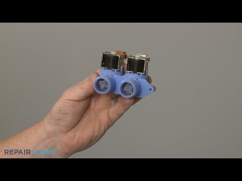
Frigidaire Electric Laundry Center Thermal Limit Replacement (134120900)
Skill Level
Total Parts Cost
$26.35Estimated Savings
$112.5009:12
- Description
This video provides step-by-step repair instructions for replacing the thermal limit on a Frigidaire electric washer/dryer laundry center (model FFLE3900UW1). The most common reason for replacing this part is if the dryer will not work.
This replacement video is applicable to the following brands:
Frigidaire
Don't forget to like and comment on this video and subscribe to our channel!
This replacement video is applicable to the following brands:
Frigidaire
Don't forget to like and comment on this video and subscribe to our channel!
Step By Step Instructions
1
Laundry Center- Model FFLE3900UW1
2
Laundry Center Thermal Limit Replacement
3
"Step 1: Gather a number two square drive bit, a phillips-head screwdriver, and needle-nose pliers. "
4
Step 2: Unplug the power cord.
5
Step 3: Have an assistant help you move the appliance away from the wall or out of the closet.
6
Step 4: Detach the venting from the dryer to fully access the rear of the laundry center.
7
Step 5: Shut off the incoming water and remove the hot and cold water supply lines as well.
8
"Step 6: If necessary, remove the drain hose from the standpipe or laundry tub."
9
"Step 7: Use the number two square drive bit or the phillips-head screwdriver to unthread the two screws securing the dryer access panel.
"
10
Step 8: Set the panel aside.
11
Step 9: Move the idler arm to the left so you can detach the belt from the motor pulley and idler pulley.
12
"Step 10: Unthread the four screws securing the rear of the top panel which will make it easier to remove the drum.
"
13
Step 11: Use the number two square drive bit or the phillips-head screwdriver to unthread the two screws securing the dryer's lower access panel.
14
Step 12: Pull the panel up to remove.
15
Step 13: Release the wires from the retaining clip and move the panel out of the way.
16
Step 14: Disconnect the dryer door switch wire connecter.
17
Step 15: Unthread the upper left screw securing the inner access panel which will make it easier to fully remove the front panel and lint filter duct assembly.
18
Step 16: Use the phillips-head screwdriver to unthread the two lower screws securing the front panel.
19
Step 17: Unthread the four upper screws along the top of the cabinet.
20
"Step 18: With all the screws unthreaded, fully remove the front panel and lint filter duct assembly. "
21
Step 19: Unthread the screw to remove the drum stop.
22
Step 20: Lift the rear of the drum up to detach the bearing from the support then carefully remove the drum from the cabinet.
23
Step 21: Use the number two square drive bit or the phillips-head screwdriver to unthread the two mounting screws securing the old thermal limit to the rear panel.
24
Step 22: Use the needle-nose pliers to help disconnect the wires.
25
"Step 23: To install the new thermal limit, connect the wires to the terminals. "
26
Step 24: Align the component on the rear panel and secure it with the screws.
27
"Step 25: With the belt looped around the drum with its grooved side facing inward, reinstall the drum, making sure the rear bearing is inserted into the bearing support. "
28
Step 26: Reposition the drum stop and thread the screw to secure.
29
Step 27: Reinstall the front panel by positioning the lower portion of the lint filter duct behind the inner access panel as you align the front panel mounting pins with the holes in the cabinet frame.
30
Step 28: Rethread the four upper screws- it will be easier to replace the two middle screws first.
31
Step 29: Rethread the two lower screws.
32
Step 30: Rethread the upper left screw to fully secure the inner access panel.
33
Step 31: Reconnect the door switch wire connecter.
34
Step 32: Secure the control panel wires in the retaining clip then reposition the panel.
35
Step 33: Replace the mounting screws.
36
Step 34: Realign the access panel and secure it with the screws.
37
"Step 35: Returning to the rear of the appliance, confirm the top panel and frame are aligned then rethread the four screws to secure.
"
38
Step 36: Loop the drum belt onto the idler and motor pullies in a zig-zag motion.
39
Step 37: Rotate the drum to help fully align the belt.
40
Step 38: Reinstall the access panel by inserting the tabs into the slots first then rethread the screws.
41
"Step 39: If necessary, reinsert the drain hose into the standpipe or hook it onto the edge of the tub. "
42
Step 40: Reattach the hot and cold water supply lines to the inlet valve ports.
43
Step 41: Reattach the venting if required and move the appliance back against the wall or into the closet.
44
Step 42: Turn the water supply back on if necessary.
Description
This video provides step-by-step repair instructions for replacing the thermal limit on a Frigidaire electric washer/dryer laundry center (model FFLE3900UW1). The most common reason for replacing this part is if the dryer will not work.
This replacement video is applicable to the following brands:
Frigidaire
Don't forget to like and comment on this video and subscribe to our channel!
This replacement video is applicable to the following brands:
Frigidaire
Don't forget to like and comment on this video and subscribe to our channel!
Step-By-Step Instructions
1
Laundry Center- Model FFLE3900UW1
2
Laundry Center Thermal Limit Replacement
3
"Step 1: Gather a number two square drive bit, a phillips-head screwdriver, and needle-nose pliers. "
4
Step 2: Unplug the power cord.
5
Step 3: Have an assistant help you move the appliance away from the wall or out of the closet.
6
Step 4: Detach the venting from the dryer to fully access the rear of the laundry center.
7
Step 5: Shut off the incoming water and remove the hot and cold water supply lines as well.
8
"Step 6: If necessary, remove the drain hose from the standpipe or laundry tub."
9
"Step 7: Use the number two square drive bit or the phillips-head screwdriver to unthread the two screws securing the dryer access panel.
"
10
Step 8: Set the panel aside.
11
Step 9: Move the idler arm to the left so you can detach the belt from the motor pulley and idler pulley.
12
"Step 10: Unthread the four screws securing the rear of the top panel which will make it easier to remove the drum.
"
13
Step 11: Use the number two square drive bit or the phillips-head screwdriver to unthread the two screws securing the dryer's lower access panel.
14
Step 12: Pull the panel up to remove.
15
Step 13: Release the wires from the retaining clip and move the panel out of the way.
16
Step 14: Disconnect the dryer door switch wire connecter.
17
Step 15: Unthread the upper left screw securing the inner access panel which will make it easier to fully remove the front panel and lint filter duct assembly.
18
Step 16: Use the phillips-head screwdriver to unthread the two lower screws securing the front panel.
19
Step 17: Unthread the four upper screws along the top of the cabinet.
20
"Step 18: With all the screws unthreaded, fully remove the front panel and lint filter duct assembly. "
21
Step 19: Unthread the screw to remove the drum stop.
22
Step 20: Lift the rear of the drum up to detach the bearing from the support then carefully remove the drum from the cabinet.
23
Step 21: Use the number two square drive bit or the phillips-head screwdriver to unthread the two mounting screws securing the old thermal limit to the rear panel.
24
Step 22: Use the needle-nose pliers to help disconnect the wires.
25
"Step 23: To install the new thermal limit, connect the wires to the terminals. "
26
Step 24: Align the component on the rear panel and secure it with the screws.
27
"Step 25: With the belt looped around the drum with its grooved side facing inward, reinstall the drum, making sure the rear bearing is inserted into the bearing support. "
28
Step 26: Reposition the drum stop and thread the screw to secure.
29
Step 27: Reinstall the front panel by positioning the lower portion of the lint filter duct behind the inner access panel as you align the front panel mounting pins with the holes in the cabinet frame.
30
Step 28: Rethread the four upper screws- it will be easier to replace the two middle screws first.
31
Step 29: Rethread the two lower screws.
32
Step 30: Rethread the upper left screw to fully secure the inner access panel.
33
Step 31: Reconnect the door switch wire connecter.
34
Step 32: Secure the control panel wires in the retaining clip then reposition the panel.
35
Step 33: Replace the mounting screws.
36
Step 34: Realign the access panel and secure it with the screws.
37
"Step 35: Returning to the rear of the appliance, confirm the top panel and frame are aligned then rethread the four screws to secure.
"
38
Step 36: Loop the drum belt onto the idler and motor pullies in a zig-zag motion.
39
Step 37: Rotate the drum to help fully align the belt.
40
Step 38: Reinstall the access panel by inserting the tabs into the slots first then rethread the screws.
41
"Step 39: If necessary, reinsert the drain hose into the standpipe or hook it onto the edge of the tub. "
42
Step 40: Reattach the hot and cold water supply lines to the inlet valve ports.
43
Step 41: Reattach the venting if required and move the appliance back against the wall or into the closet.
44
Step 42: Turn the water supply back on if necessary.
Applicable Product Model
Parts Needed
Thermal Fuse
$26.35
Total$0.00
Related Articles & Videos
07:04
Part Replacement
Frigidaire Electric Laundry Center Dryer Drum Belt Replacement (134503600)
18:36
Part Replacement
Frigidaire Laundry Center Washer Transmission Assembly Replacement (5304517318)
10:24
Part Replacement
Frigidaire Electric Laundry Center Heater Assembly Replacement (137392702)
04:37
Part Replacement
Frigidaire Laundry Center Water Inlet Valve Replacement (5304515818)


Our Story
Family-owned and operated since 1912, Burke America Parts Group is the longest-running genuine appliance, HVAC, and outdoor power equipment parts solution in North America. At Repair Clinic, we're proud to be an international brand trusted by the pros as well as the DIY community.
About Repair Clinic
© 2026 RepairClinic.com