

Price Match Guarantee

In-stock parts ship the same day

365-Day Return Policy
Price Match GuaranteeGET PRO PRICING
Video & Articles: Appliance & Equipment RepairBriggs & Stratton Small Engine Crankcase Oil Seal Replacement 299819S 

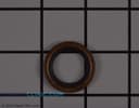
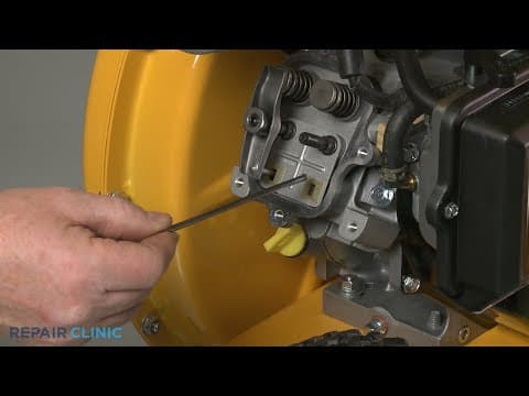
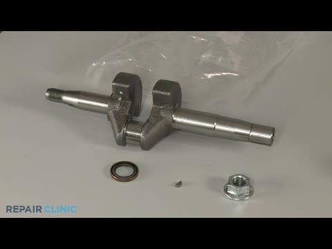
Briggs & Stratton Small Engine Crankcase Oil Seal Replacement 299819S
Skill Level
Total Parts Cost
$6.42Estimated Savings
$112.5029:18
- Description
This video provides step-by-step instructions for replacing the crankcase oil seal on a Briggs & Stratton small engine. The most common reason for replacing this part is if the engine is leaking oil.
All of the information in this video is applicable to the following brands: Briggs & Stratton
All of the information in this video is applicable to the following brands: Briggs & Stratton
Step By Step Instructions
1
To replace the crankcase oil seal on this briggs and stratton engine, you will need to uninstall the engine from the equipment it’s powering.
2
If the engine is installed on this cub cadet chipper shredder…
3
… you will need these tools to fully uninstall the engine.
4
To replace the oil seal, you will need these additional tools.
5
Before you begin this procedure, make sure the engine has cooled.
6
We also recommend there be no fuel in the tank or oil in the engine.
7
Use the half-inch wrench to secure the bolts and the half-inch socket to unthread the nuts securing the hopper assembly support plate to the impeller housing.
8
Using the half-inch socket, unthread the six mounting nuts securing the front of the hopper assembly to the housing.
9
With the nuts unthreaded, tilt the hopper assembly back and lift up to fully detach the assembly from the bolts.
10
Remove the shredder plate.
11
Next, unthread the two retaining knob screws securing the bottom of the discharge chute.
12
Use the 7/16th inch wrench to secure the chute’s mounting bolt…
13
… then use the 7/16th inch socket to fully unthread the nut.
14
Slide out the bolt, detach the chute, and remove the two spacers.
15
Use the needle-nose pliers to pull out the retaining pin securing the shredder screen pin and slide the pin out.
16
Next, use the half-inch socket, the small flat-head screwdriver, and the needle-nose pliers to remove the upper mounting screws securing the outer flail housing.
17
With the tow bar installed, tip the chipper shredder back and set a weight on the tow bar to hold it down.
18
Now, using the half-inch socket and the half-inch wrench, remove the ten remaining nuts and bolts securing the outer housing to the inner housing.
19
With all the nuts and bolts uninstalled, fully detach the outer flail housing and set the shredder screen aside.
20
Use the two-by-four piece of wood to prevent the impeller from rotating.
21
Use the 9/16th inch six-point socket with a half-inch driver to unthread the center mounting bolt securing the shredder blade and impeller – this will require some effort.
22
Reposition the wood support to secure the impeller.
23
Now use the 5/8th inch socket to thread the impeller removal tool into the center bolt screw hole.
24
The bottom of the tool will then push against the bottom of the engine shaft to detach the impeller from the shaft.
25
Once detached, unthread the impeller removal tool.
26
Return the chipper shredder to its upright position.
27
Now pull out the retaining pin securing the tow bar clevis pin.
28
Slide out the clevis pin and remove the bar.
29
Tip the chipper shredder back.
30
Use the half-inch wrench and the half-inch socket to remove the nut and bolt securing the left rear corner of the engine base.
31
Use the half-inch socket to unthread the three remaining mounting bolts securing the base.
32
Return the chipper shredder to its upright position.
33
Next, unthread the four mounting bolts securing the engine to the inner flail housing.
34
With the bolts unthreaded, you can now fully remove the engine…
35
… and set it upright on a sturdy surface.
36
Use the 5/16th inch nut driver to unthread the two mounting screws securing the air filter cover.
37
Remove the cover and the air filter…
38
…then unthread the screws securing the filter base.
39
Pull the choke lever off so you can move the base out of the way.
40
Using the 5/16th inch nut driver, unthread the two screws securing the throttle cover plate.
41
Shift the throttle lever to the right so you can detach the plate.
42
You can now unthread the three screws securing the blower housing using the 10mm socket.
43
Set the blower housing aside…
44
… and detach the spark plug wire and boot from the spark plug.
45
Use the 5/8th inch spark plug wrench to help loosen the spark plug then unthread it.
46
Confirm the engine piston is in the “down” position…
47
… then insert a cord into the cylinder to prevent the piston from moving.
48
You can now use the 15/16th inch socket and a mallet to loosen the flywheel mounting nut.
49
Fully unthread the nut and remove the starter cup and fan.
50
Your next step is to use the dedicated flywheel puller to detach the flywheel.
51
Partially rethread the mounting nut on the engine shaft.
52
Position the flywheel puller and thread the bolts into the flywheel.
53
Use the half-wrench to help tighten.
54
Next, thread the rear nuts so they’re flush against the flywheel.
55
Now tighten the front nuts until the flywheel becomes detached.
56
Remove the puller.
57
Unthread the nut and slide off the flywheel.
58
Remove the cord from the cylinder…
59
… then set the engine on its side so the crankcase cover is facing up.
60
Detach the breather tube from the rocker cover.
61
Now use the 10mm socket to unthread the four mounting screws securing the rocker cover to the cylinder head.
62
You will need to use the 3/8th inch universal joint adapter to unthread the top screw.
63
With the four screws unthreaded, you can detach the cover and gasket if loose.
64
Confirm the engine piston is in the “up” position, known as the “top dead center”, then lower the piston slightly, making sure both rocker arms stay loose.
65
Use the 5/8th inch wrench to secure the intake rocker arm adjuster nut and the 5/32nd inch allen wrench to loosen the set screw.
66
Partially unthread the adjuster nut enough to rotate the arm out of the way then slide out the push rod.
67
Now repeat to rotate the exhaust valve rocker arm out of the way and remove the push rod.
68
Next, use the 10mm socket to unthread the six mounting screws securing the crankcase cover.
69
You can use a flat-head screwdriver to help pry off the cover.
70
With the piston in the “up” position, lift out the camshaft…
71
… and remove the two tappet valves.
72
If necessary, rotate the crankshaft so you can access the two mounting screws securing the connecting rod cap.
73
Use the 8mm socket to unthread them.
74
Detach the cap.
75
Move the piston back to the “up” or “top dead center” position and push the piston so you can slide out the crankshaft.
76
You can now use the small flat-head screwdriver and mallet to knock out the old oil seal.
77
To install the new oil seal…
78
… insert it into the hole in the crankcase.
79
You can use the mallet to help keep it flush with the crankcase.
80
Next, slide small and large washers over a long bolt along with a small flywheel puller brace or a flat piece of wood or metal.
81
Insert the bolt through the hole in the crankcase…
82
… then align a 19mm socket or one slightly larger, and another small washer.
83
Thread and tighten a nut to fully seat the oil seal.
84
With the seal secured, unthread the nut and remove the brace, bolt, socket, and washers.
85
Lubricate the crank pin journal as well as the smaller end of the crankshaft then insert that end through the hole in the crankcase on the power take off side.
86
Set the engine on its side…
87
… then push the piston and connecting rod down so you can align the crankshaft cap… and thread the screws.
88
Using the 8mm socket on a torque wrench, torque the screws to 100 inch pounds.
89
Reseat the tappet valves.
90
Remove the timing gear washer so you can see the indent mark on the gear.
91
Reinstall the camshaft so the indent mark on the gear aligns with the indent mark on the timing gear when the gear teeth interlock.
92
You may need to rotate the crankshaft to align the marks.
93
Replace the washer.
94
Confirm the crankcase gasket is intact, then realign the cover.
95
Thread the mounting screws in a diagonal order.
96
Using the 10mm socket on a torque wrench, torque the screws to 100 inch pounds.
97
Set the engine upright.
98
Insert both push rods through the guide until they are fully seated in the cylinder head… then realign the rocker arms and partially tighten the adjuster nuts.
99
Now use the feeler gauge to set the appropriate gap between both rocker arms and their respective valve caps – the intake rocker arm gap should be between .004 and .006 thousandths of an inch…
100
… the exhaust rocker arm gap should be between .009 and .011 thousandths of an inch.
101
Tighten both rocker arm adjuster set screws then recheck the gaps.
102
Reinstall the rocker cover by inserting the top mounting screw then slide the gasket, if applicable, over the screw.
103
Align the cover and gasket on the cylinder head and thread the screw.
104
Replace the remaining screws to fully secure the cover.
105
The longer screw goes on the bottom.
106
Keeping the air filter base attached, insert the breather tube into the hole in the rocker cover.
107
Reinsert the cord into the cylinder to prevent the piston from moving.
108
Position the flywheel on the shaft…
109
… then insert the flywheel key.
110
Align the fan and the starter cup…
111
… then thread and tighten the provided nut.
112
Using the 15/16th inch socket on the torque wrench, torque the nut to sixty foot pounds.
113
Remove the cord from the cylinder…
114
… and rethread the spark plug.
115
Be careful not to damage the threads by overtightening.
116
Reattach the wire and boot to the spark plug.
117
Now reposition the blower housing…
118
… and rethread the three mounting screws.
119
Reposition the throttle cover plate…
120
… and rethread the screws.
121
Insert the two mounting screws through the air filter base…
122
… then align the base and thread the screws into the carburetor.
123
Replace the choke lever.
124
With the pre- cleaner positioned in the cover followed by the air filter with its rubber gasket facing outward…
125
… align the cover on the base…
126
… and secure it with the screws.
127
Reinstall the engine by positioning it on the chipper shredder base with the crankshaft inserted through the hole in the inner flail housing.
128
Confirm the washers are on the screws, then loosely thread the four screws to secure the engine to the flail housing.
129
Tip the chipper shredder back…
130
… then thread and tighten the three mounting bolts to secure the engine base to the base of the chipper shredder.
131
Next, confirm the star washer is aligned on the left rear bolt then insert the bolt… slide on the round washer then thread and tighten the nut to secure the left rear corner of the engine base.
132
Set the equipment upright…
133
… then tighten the four screws securing the engine to the inner flail housing.
134
Keeping the hitch plates tilted downward, reinsert the tow bar into the mounting bracket.
135
Slide in the clevis pin and secure it with the retaining pin.
136
With the tow bar reinstalled, tip the chipper shredder back and support it.
137
Reinstall the impeller assembly by aligning it on the engine shaft.
138
Secure it with the wood support, then rethread the center mounting bolt.
139
Using the 9/16th inch six-point socket on a torque wrench, torque the center bolt to fifty foot pounds.
140
Remove the wood.
141
Position the shredder screen mounting post in the hole in the inner flail housing then realign the outer housing.
142
Thread and tighten the ten nuts and bolts to secure.
143
Rethread the two upper mounting screws using the speed clips.
144
Remove the weight and return the chipper shredder to its upright position.
145
Slide the shredder screen pin through the impeller housing and screen.
146
Insert the retaining pin to secure.
147
Realign the discharge chute on the impeller housing and insert the spacers.
148
Insert the mounting bolt…
149
… then thread and tighten the nut.
150
Fully position the chute then thread and tighten the retaining knob screws.
151
Realign the shredder plate on the six impeller housing bolts.
152
Reinstall the hopper assembly by aligning the support plate on the two upper mounting bolts first then rotate the assembly to align it on the impeller housing bolts.
153
Thread and tighten all eight mounting nuts to secure – we recommend hand-threading the nuts first then using the socket to tighten once all the nuts are in place.
154
Refill the fuel tank, add oil, and the engine should be ready for use.
Description
This video provides step-by-step instructions for replacing the crankcase oil seal on a Briggs & Stratton small engine. The most common reason for replacing this part is if the engine is leaking oil.
All of the information in this video is applicable to the following brands: Briggs & Stratton
All of the information in this video is applicable to the following brands: Briggs & Stratton
Step-By-Step Instructions
1
To replace the crankcase oil seal on this briggs and stratton engine, you will need to uninstall the engine from the equipment it’s powering.
2
If the engine is installed on this cub cadet chipper shredder…
3
… you will need these tools to fully uninstall the engine.
4
To replace the oil seal, you will need these additional tools.
5
Before you begin this procedure, make sure the engine has cooled.
6
We also recommend there be no fuel in the tank or oil in the engine.
7
Use the half-inch wrench to secure the bolts and the half-inch socket to unthread the nuts securing the hopper assembly support plate to the impeller housing.
8
Using the half-inch socket, unthread the six mounting nuts securing the front of the hopper assembly to the housing.
9
With the nuts unthreaded, tilt the hopper assembly back and lift up to fully detach the assembly from the bolts.
10
Remove the shredder plate.
11
Next, unthread the two retaining knob screws securing the bottom of the discharge chute.
12
Use the 7/16th inch wrench to secure the chute’s mounting bolt…
13
… then use the 7/16th inch socket to fully unthread the nut.
14
Slide out the bolt, detach the chute, and remove the two spacers.
15
Use the needle-nose pliers to pull out the retaining pin securing the shredder screen pin and slide the pin out.
16
Next, use the half-inch socket, the small flat-head screwdriver, and the needle-nose pliers to remove the upper mounting screws securing the outer flail housing.
17
With the tow bar installed, tip the chipper shredder back and set a weight on the tow bar to hold it down.
18
Now, using the half-inch socket and the half-inch wrench, remove the ten remaining nuts and bolts securing the outer housing to the inner housing.
19
With all the nuts and bolts uninstalled, fully detach the outer flail housing and set the shredder screen aside.
20
Use the two-by-four piece of wood to prevent the impeller from rotating.
21
Use the 9/16th inch six-point socket with a half-inch driver to unthread the center mounting bolt securing the shredder blade and impeller – this will require some effort.
22
Reposition the wood support to secure the impeller.
23
Now use the 5/8th inch socket to thread the impeller removal tool into the center bolt screw hole.
24
The bottom of the tool will then push against the bottom of the engine shaft to detach the impeller from the shaft.
25
Once detached, unthread the impeller removal tool.
26
Return the chipper shredder to its upright position.
27
Now pull out the retaining pin securing the tow bar clevis pin.
28
Slide out the clevis pin and remove the bar.
29
Tip the chipper shredder back.
30
Use the half-inch wrench and the half-inch socket to remove the nut and bolt securing the left rear corner of the engine base.
31
Use the half-inch socket to unthread the three remaining mounting bolts securing the base.
32
Return the chipper shredder to its upright position.
33
Next, unthread the four mounting bolts securing the engine to the inner flail housing.
34
With the bolts unthreaded, you can now fully remove the engine…
35
… and set it upright on a sturdy surface.
36
Use the 5/16th inch nut driver to unthread the two mounting screws securing the air filter cover.
37
Remove the cover and the air filter…
38
…then unthread the screws securing the filter base.
39
Pull the choke lever off so you can move the base out of the way.
40
Using the 5/16th inch nut driver, unthread the two screws securing the throttle cover plate.
41
Shift the throttle lever to the right so you can detach the plate.
42
You can now unthread the three screws securing the blower housing using the 10mm socket.
43
Set the blower housing aside…
44
… and detach the spark plug wire and boot from the spark plug.
45
Use the 5/8th inch spark plug wrench to help loosen the spark plug then unthread it.
46
Confirm the engine piston is in the “down” position…
47
… then insert a cord into the cylinder to prevent the piston from moving.
48
You can now use the 15/16th inch socket and a mallet to loosen the flywheel mounting nut.
49
Fully unthread the nut and remove the starter cup and fan.
50
Your next step is to use the dedicated flywheel puller to detach the flywheel.
51
Partially rethread the mounting nut on the engine shaft.
52
Position the flywheel puller and thread the bolts into the flywheel.
53
Use the half-wrench to help tighten.
54
Next, thread the rear nuts so they’re flush against the flywheel.
55
Now tighten the front nuts until the flywheel becomes detached.
56
Remove the puller.
57
Unthread the nut and slide off the flywheel.
58
Remove the cord from the cylinder…
59
… then set the engine on its side so the crankcase cover is facing up.
60
Detach the breather tube from the rocker cover.
61
Now use the 10mm socket to unthread the four mounting screws securing the rocker cover to the cylinder head.
62
You will need to use the 3/8th inch universal joint adapter to unthread the top screw.
63
With the four screws unthreaded, you can detach the cover and gasket if loose.
64
Confirm the engine piston is in the “up” position, known as the “top dead center”, then lower the piston slightly, making sure both rocker arms stay loose.
65
Use the 5/8th inch wrench to secure the intake rocker arm adjuster nut and the 5/32nd inch allen wrench to loosen the set screw.
66
Partially unthread the adjuster nut enough to rotate the arm out of the way then slide out the push rod.
67
Now repeat to rotate the exhaust valve rocker arm out of the way and remove the push rod.
68
Next, use the 10mm socket to unthread the six mounting screws securing the crankcase cover.
69
You can use a flat-head screwdriver to help pry off the cover.
70
With the piston in the “up” position, lift out the camshaft…
71
… and remove the two tappet valves.
72
If necessary, rotate the crankshaft so you can access the two mounting screws securing the connecting rod cap.
73
Use the 8mm socket to unthread them.
74
Detach the cap.
75
Move the piston back to the “up” or “top dead center” position and push the piston so you can slide out the crankshaft.
76
You can now use the small flat-head screwdriver and mallet to knock out the old oil seal.
77
To install the new oil seal…
78
… insert it into the hole in the crankcase.
79
You can use the mallet to help keep it flush with the crankcase.
80
Next, slide small and large washers over a long bolt along with a small flywheel puller brace or a flat piece of wood or metal.
81
Insert the bolt through the hole in the crankcase…
82
… then align a 19mm socket or one slightly larger, and another small washer.
83
Thread and tighten a nut to fully seat the oil seal.
84
With the seal secured, unthread the nut and remove the brace, bolt, socket, and washers.
85
Lubricate the crank pin journal as well as the smaller end of the crankshaft then insert that end through the hole in the crankcase on the power take off side.
86
Set the engine on its side…
87
… then push the piston and connecting rod down so you can align the crankshaft cap… and thread the screws.
88
Using the 8mm socket on a torque wrench, torque the screws to 100 inch pounds.
89
Reseat the tappet valves.
90
Remove the timing gear washer so you can see the indent mark on the gear.
91
Reinstall the camshaft so the indent mark on the gear aligns with the indent mark on the timing gear when the gear teeth interlock.
92
You may need to rotate the crankshaft to align the marks.
93
Replace the washer.
94
Confirm the crankcase gasket is intact, then realign the cover.
95
Thread the mounting screws in a diagonal order.
96
Using the 10mm socket on a torque wrench, torque the screws to 100 inch pounds.
97
Set the engine upright.
98
Insert both push rods through the guide until they are fully seated in the cylinder head… then realign the rocker arms and partially tighten the adjuster nuts.
99
Now use the feeler gauge to set the appropriate gap between both rocker arms and their respective valve caps – the intake rocker arm gap should be between .004 and .006 thousandths of an inch…
100
… the exhaust rocker arm gap should be between .009 and .011 thousandths of an inch.
101
Tighten both rocker arm adjuster set screws then recheck the gaps.
102
Reinstall the rocker cover by inserting the top mounting screw then slide the gasket, if applicable, over the screw.
103
Align the cover and gasket on the cylinder head and thread the screw.
104
Replace the remaining screws to fully secure the cover.
105
The longer screw goes on the bottom.
106
Keeping the air filter base attached, insert the breather tube into the hole in the rocker cover.
107
Reinsert the cord into the cylinder to prevent the piston from moving.
108
Position the flywheel on the shaft…
109
… then insert the flywheel key.
110
Align the fan and the starter cup…
111
… then thread and tighten the provided nut.
112
Using the 15/16th inch socket on the torque wrench, torque the nut to sixty foot pounds.
113
Remove the cord from the cylinder…
114
… and rethread the spark plug.
115
Be careful not to damage the threads by overtightening.
116
Reattach the wire and boot to the spark plug.
117
Now reposition the blower housing…
118
… and rethread the three mounting screws.
119
Reposition the throttle cover plate…
120
… and rethread the screws.
121
Insert the two mounting screws through the air filter base…
122
… then align the base and thread the screws into the carburetor.
123
Replace the choke lever.
124
With the pre- cleaner positioned in the cover followed by the air filter with its rubber gasket facing outward…
125
… align the cover on the base…
126
… and secure it with the screws.
127
Reinstall the engine by positioning it on the chipper shredder base with the crankshaft inserted through the hole in the inner flail housing.
128
Confirm the washers are on the screws, then loosely thread the four screws to secure the engine to the flail housing.
129
Tip the chipper shredder back…
130
… then thread and tighten the three mounting bolts to secure the engine base to the base of the chipper shredder.
131
Next, confirm the star washer is aligned on the left rear bolt then insert the bolt… slide on the round washer then thread and tighten the nut to secure the left rear corner of the engine base.
132
Set the equipment upright…
133
… then tighten the four screws securing the engine to the inner flail housing.
134
Keeping the hitch plates tilted downward, reinsert the tow bar into the mounting bracket.
135
Slide in the clevis pin and secure it with the retaining pin.
136
With the tow bar reinstalled, tip the chipper shredder back and support it.
137
Reinstall the impeller assembly by aligning it on the engine shaft.
138
Secure it with the wood support, then rethread the center mounting bolt.
139
Using the 9/16th inch six-point socket on a torque wrench, torque the center bolt to fifty foot pounds.
140
Remove the wood.
141
Position the shredder screen mounting post in the hole in the inner flail housing then realign the outer housing.
142
Thread and tighten the ten nuts and bolts to secure.
143
Rethread the two upper mounting screws using the speed clips.
144
Remove the weight and return the chipper shredder to its upright position.
145
Slide the shredder screen pin through the impeller housing and screen.
146
Insert the retaining pin to secure.
147
Realign the discharge chute on the impeller housing and insert the spacers.
148
Insert the mounting bolt…
149
… then thread and tighten the nut.
150
Fully position the chute then thread and tighten the retaining knob screws.
151
Realign the shredder plate on the six impeller housing bolts.
152
Reinstall the hopper assembly by aligning the support plate on the two upper mounting bolts first then rotate the assembly to align it on the impeller housing bolts.
153
Thread and tighten all eight mounting nuts to secure – we recommend hand-threading the nuts first then using the socket to tighten once all the nuts are in place.
154
Refill the fuel tank, add oil, and the engine should be ready for use.
Applicable Product Model
Parts Needed
Oil Seal
$6.42
Total$0.00
Related Articles & Videos
32:00
Part Replacement
Briggs & Stratton Small Engine Piston Ring Set Replacement 791787
14:43
Part Replacement
Briggs & Stratton Small Engine Intake Valve Seal Replacement 795440




Our Story
Family-owned and operated since 1912, Burke America Parts Group is the longest-running genuine appliance, HVAC, and outdoor power equipment parts solution in North America. At Repair Clinic, we're proud to be an international brand trusted by the pros as well as the DIY community.
About Repair Clinic
© 2026 RepairClinic.com