

Price Match Guarantee

In-stock parts ship the same day

365-Day Return Policy
Price Match GuaranteeGET PRO PRICING
Video & Articles: Appliance & Equipment RepairGE Dryer Main Wire Harness Assembly Replacement WE15X25654

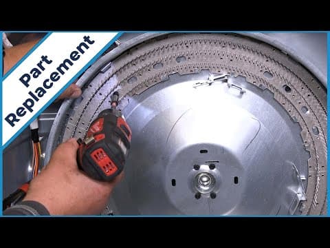
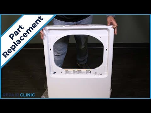
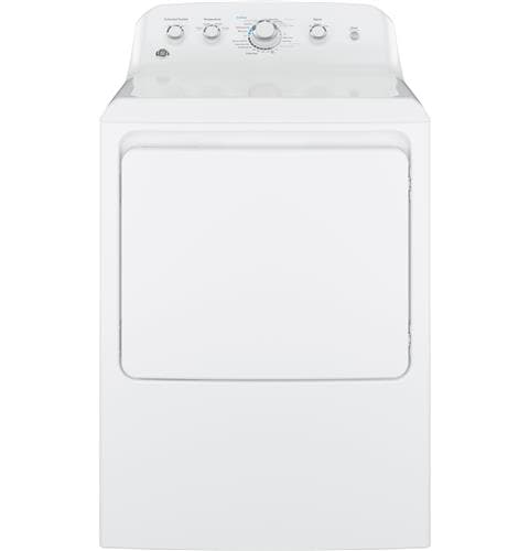
This video provides step-by-step repair instructions for replacing the main wire harness assembly in a GE dryer (Model GTD42EASJ2WW). The most common reason for replacing this part is if it's missing or broken.
This replacement video is applicable to the following brands:
GE
Screws affiliated with dryer-
Don't forget to like and comment on this video and subscribe to our channel!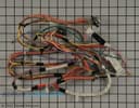
GE Dryer Main Wire Harness Assembly Replacement WE15X25654
Skill Level
Total Parts Cost
$185.20Estimated Savings
$112.5023:22
- Description
This video provides step-by-step repair instructions for replacing the main wire harness assembly in a GE dryer (Model GTD42EASJ2WW). The most common reason for replacing this part is if it's missing or broken.
This replacement video is applicable to the following brands:
GE
Screws affiliated with dryer-
Don't forget to like and comment on this video and subscribe to our channel!
Step By Step Instructions
1
To replace the main wire harness assembly in your ge dryer, you will need a drill driver with a 1/4” bit, a #1 square head bit, a #2 square head bit, and needlenose pliers.
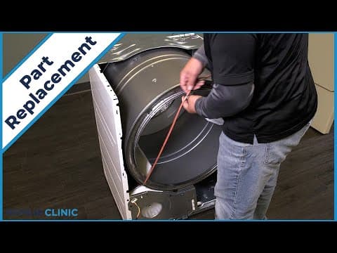
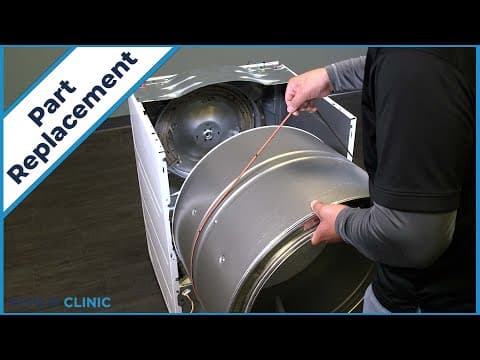
2
Before you begin the procedure, unplug the power to the appliance.
3
Unthread the screw on the back panel to remove the protective cover.
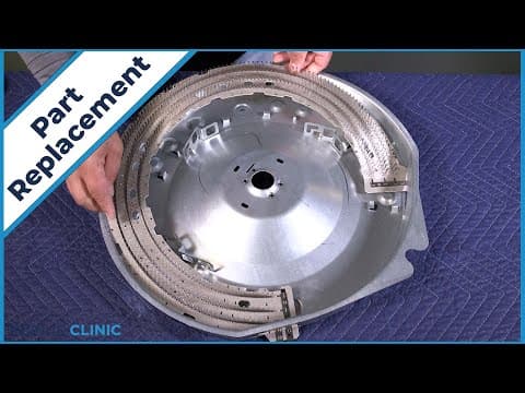
4
Loosen the screws on the block terminal to free the power supply wires, noting the orientation, unplug the yellow, red, and black wires, feed them through to the inside of the panel.
5
Unthread the five screws on the panel. any missing screws can be ordered through the links in the description below.
6
Pull out and lift the panel from the backsplash.
7
Detatch the ground wire.
8
Unthread the two screws that secure the backsplash.
9
Pull the backsplash back, and lift up to free it from the dryer.
10
Note the orientation of the wires.
11
Detatch the purple, brown, and red wires from the start switch.
12
Now detatch the red wire from the signal switch.
13
Detatch the purple, brown, yellow, and red wires from the timer.
14
Detatch the blue, yellow, brown, and bottom orange wires from the temperature switch.
15
Detatch the brown wire from the extended tumble switch.
16
Unthread the screw and remove the resistor.
17
Unthread the two screws securing both the top panel plates.
18
Detatch the solid brown wire from the purple wire.
19
Feed the wires through the panel.
20
Unthread the two screws on the top of the panel, then unthread the two screws under the lip of the door threshold.
21
Lift the top panel from the appliance.
22
Unthread the two screws securing the front panel.
23
Pull the panel back and unplug the two wire harnesses.
24
Lift the panel off the three tabs, depress the pulley to release the tension on the belt and unthread the belt from the pulley and motor shaft.
25
Use the belt to lift out the drum assembly
26
Remove the wires from the cycling thermostat, the safety thermostat, and high limit thermostat.
27
Noting the orientation, remove the blue and brown wires from the lower left side of the element and the purple wire from the lower right side.
28
Unthread the four screws holding the heating assembly, and move it to a flat surface.
29
Note the positions of the cycling thermostat and the saftey thermostat.
30
And unthread the screws securing them to the housing.
31
Unthread the two screws to remove the blower thermostat.
32
Unthread the two screws that secure the side panel to the blower housing and base.
33
Unclip and feed the light and door switch wires through the blower housing.
34
Lift the dryer and pinch the retaining clip to remove it.
35
Now unthread the remaining six screws along the perimeter of the side panel.
36
Lift the cover to slide the panel out.
37
Slide the idler arm from underneath the retaing bracket. lift the arm and slide the other end from the blower housing.
38
Unplug the harness from the motor.
39
Unthread the ground screw.
40
Remove the wires from the retaining clip.
41
Unthread the two screws on the dryer belt switch.
42
Pinch and remove the four wire retaining clips on the back panel.
43
Unthread the two retaining clips.
44
Remove the harness from the machine.
45
To install the new main wire harness assembly, noting the orientation, unplug the thermostats from the harness.
46
Rethread the two screws that secure the harness to the back panel.
47
Reattatch the 2 thermostats to the heating assembly.
48
Align the element assembly with its four mounting holes and rethread the screws.
49
Snap in the four retaining clips to the back panel.
50
Feed the power block wires through the back of the panel.
51
Rethread the two screws to mount the belt switch.
52
Set the wire harness in the retaining clip.
53
Rethread the grounding screw.
54
Plug in the harness to the motor.
55
insert the end of the arm in the blower housing then place the arm under the retaining bracket, make sure the idler arm is able to operate the switch.
56
Snap the retaining clip in the bottom of the dryer.
57
Mount and rethread the screws to secure the new blower thermostat.
58
Plug the wires into the thermostat.
59
Rethread the six screws along the perimeter of the panel, feed the wires of the light and door switch through the blower housing and secure with the clip, now rethread the two screws to the blower housing and base to secure it.
60
Plug in the purple element wire, then the blue and brown element wires.
61
Plug the four wires into the cycling thermostat.
62
Then the orange wires into the saftey thermostat, and the purple wires into the high limit thermostat.
63
Place the drum inside the dryer and line up the drum shaft and bearing with the bearing retainer on the rear panel.
64
Make sure the belt is ribside down along outside of the drum.
65
Loop the belt around the tension pulley and motor shaft in a zig-zag formation.
66
Rotate the drum to help align the belt.
67
Set the front panel on the three tabs, then plug in the two wire harnesses.
68
Push the panel forward, then secure it with the two screws.
69
Set the panel on the appliance and feed the wires through.
70
Hook the back of the top panel and adjust it till it is aligned.
71
Rethread the two screws under the door threshold, as well as the two screws on the top of the panel.
72
Reattach the solid brown wire to the purple wire.
73
Slide the top plates into position and secure with the two screws.
74
Rethread the screw to secure the resistor.
75
Reattach the brown wire into the extended tumble switch.
76
Reattach the blue, yellow, brown, and bottom orange wires into the temperature switch.
77
Reattach the purple, brown, yellow, and red wires into the timer.
78
Reattach the red wire into the signal switch.
79
Reattach the purple, brown, and red wires to the start switch.
80
Set the backsplash back into the dryer slots and push forward to lock in place.
81
Rethread the two screws.
82
Reattach the ground wire to the panel.
83
Insert the panel tabs into the slots on the dryer.
84
Rethread the five screws.
85
Plug in the wires to the terminal.
86
Reattach the power wires to the terminal and tighten the screws to secure.
87
Position the protective cover and rethread the screw.
88
Plug in the dryer, and your dryer should be ready for use.
Description
This video provides step-by-step repair instructions for replacing the main wire harness assembly in a GE dryer (Model GTD42EASJ2WW). The most common reason for replacing this part is if it's missing or broken.
This replacement video is applicable to the following brands:
GE
Screws affiliated with dryer-
Don't forget to like and comment on this video and subscribe to our channel!
Step-By-Step Instructions
1
To replace the main wire harness assembly in your ge dryer, you will need a drill driver with a 1/4” bit, a #1 square head bit, a #2 square head bit, and needlenose pliers.
2
Before you begin the procedure, unplug the power to the appliance.
3
Unthread the screw on the back panel to remove the protective cover.
4
Loosen the screws on the block terminal to free the power supply wires, noting the orientation, unplug the yellow, red, and black wires, feed them through to the inside of the panel.
5
Unthread the five screws on the panel. any missing screws can be ordered through the links in the description below.
6
Pull out and lift the panel from the backsplash.
7
Detatch the ground wire.
8
Unthread the two screws that secure the backsplash.
9
Pull the backsplash back, and lift up to free it from the dryer.
10
Note the orientation of the wires.
11
Detatch the purple, brown, and red wires from the start switch.
12
Now detatch the red wire from the signal switch.
13
Detatch the purple, brown, yellow, and red wires from the timer.
14
Detatch the blue, yellow, brown, and bottom orange wires from the temperature switch.
15
Detatch the brown wire from the extended tumble switch.
16
Unthread the screw and remove the resistor.
17
Unthread the two screws securing both the top panel plates.
18
Detatch the solid brown wire from the purple wire.
19
Feed the wires through the panel.
20
Unthread the two screws on the top of the panel, then unthread the two screws under the lip of the door threshold.
21
Lift the top panel from the appliance.
22
Unthread the two screws securing the front panel.
23
Pull the panel back and unplug the two wire harnesses.
24
Lift the panel off the three tabs, depress the pulley to release the tension on the belt and unthread the belt from the pulley and motor shaft.
25
Use the belt to lift out the drum assembly
26
Remove the wires from the cycling thermostat, the safety thermostat, and high limit thermostat.
27
Noting the orientation, remove the blue and brown wires from the lower left side of the element and the purple wire from the lower right side.
28
Unthread the four screws holding the heating assembly, and move it to a flat surface.
29
Note the positions of the cycling thermostat and the saftey thermostat.
30
And unthread the screws securing them to the housing.
31
Unthread the two screws to remove the blower thermostat.
32
Unthread the two screws that secure the side panel to the blower housing and base.
33
Unclip and feed the light and door switch wires through the blower housing.
34
Lift the dryer and pinch the retaining clip to remove it.
35
Now unthread the remaining six screws along the perimeter of the side panel.
36
Lift the cover to slide the panel out.
37
Slide the idler arm from underneath the retaing bracket. lift the arm and slide the other end from the blower housing.
38
Unplug the harness from the motor.
39
Unthread the ground screw.
40
Remove the wires from the retaining clip.
41
Unthread the two screws on the dryer belt switch.
42
Pinch and remove the four wire retaining clips on the back panel.
43
Unthread the two retaining clips.
44
Remove the harness from the machine.
45
To install the new main wire harness assembly, noting the orientation, unplug the thermostats from the harness.
46
Rethread the two screws that secure the harness to the back panel.
47
Reattatch the 2 thermostats to the heating assembly.
48
Align the element assembly with its four mounting holes and rethread the screws.
49
Snap in the four retaining clips to the back panel.
50
Feed the power block wires through the back of the panel.
51
Rethread the two screws to mount the belt switch.
52
Set the wire harness in the retaining clip.
53
Rethread the grounding screw.
54
Plug in the harness to the motor.
55
insert the end of the arm in the blower housing then place the arm under the retaining bracket, make sure the idler arm is able to operate the switch.
56
Snap the retaining clip in the bottom of the dryer.
57
Mount and rethread the screws to secure the new blower thermostat.
58
Plug the wires into the thermostat.
59
Rethread the six screws along the perimeter of the panel, feed the wires of the light and door switch through the blower housing and secure with the clip, now rethread the two screws to the blower housing and base to secure it.
60
Plug in the purple element wire, then the blue and brown element wires.
61
Plug the four wires into the cycling thermostat.
62
Then the orange wires into the saftey thermostat, and the purple wires into the high limit thermostat.
63
Place the drum inside the dryer and line up the drum shaft and bearing with the bearing retainer on the rear panel.
64
Make sure the belt is ribside down along outside of the drum.
65
Loop the belt around the tension pulley and motor shaft in a zig-zag formation.
66
Rotate the drum to help align the belt.
67
Set the front panel on the three tabs, then plug in the two wire harnesses.
68
Push the panel forward, then secure it with the two screws.
69
Set the panel on the appliance and feed the wires through.
70
Hook the back of the top panel and adjust it till it is aligned.
71
Rethread the two screws under the door threshold, as well as the two screws on the top of the panel.
72
Reattach the solid brown wire to the purple wire.
73
Slide the top plates into position and secure with the two screws.
74
Rethread the screw to secure the resistor.
75
Reattach the brown wire into the extended tumble switch.
76
Reattach the blue, yellow, brown, and bottom orange wires into the temperature switch.
77
Reattach the purple, brown, yellow, and red wires into the timer.
78
Reattach the red wire into the signal switch.
79
Reattach the purple, brown, and red wires to the start switch.
80
Set the backsplash back into the dryer slots and push forward to lock in place.
81
Rethread the two screws.
82
Reattach the ground wire to the panel.
83
Insert the panel tabs into the slots on the dryer.
84
Rethread the five screws.
85
Plug in the wires to the terminal.
86
Reattach the power wires to the terminal and tighten the screws to secure.
87
Position the protective cover and rethread the screw.
88
Plug in the dryer, and your dryer should be ready for use.
Applicable Product Model
Parts Needed
Wire Harness
$185.20
Total$0.00
Related Articles & Videos




Our Story
Family-owned and operated since 1912, Burke America Parts Group is the longest-running genuine appliance, HVAC, and outdoor power equipment parts solution in North America. At Repair Clinic, we're proud to be an international brand trusted by the pros as well as the DIY community.
About Repair Clinic
© 2026 RepairClinic.com