

Price Match Guarantee

In-stock parts ship the same day

365-Day Return Policy
Price Match GuaranteeGET PRO PRICING
Video & Articles: Appliance & Equipment RepairWhirlpool Alpha Electric Dryer Vent Kit Installation #W10323246

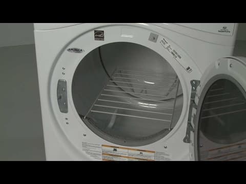
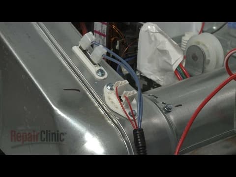
Whirlpool Alpha Electric Dryer Vent Kit Installation #W10323246
Skill Level
Total Parts Cost
$70.94Estimated Savings
$112.5011:47
- Description
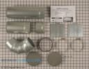
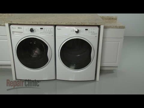
This video provides step-by-step repair instructions for installing the vent kit on a Whirlpool electric dryer (model #WED85HEFW0). The vent kit can be used to to route the dryer exhaust vent in a different orientation.
This vent kit installation video is applicable to the following brands:
Whirlpool, Maytag
Tools needed: T-25 Torx bit, Phillips-head screwdriver, 1/4" socket
Don't forget to like and comment on this video and subscribe to our channel!
This vent kit installation video is applicable to the following brands:
Whirlpool, Maytag
Tools needed: T-25 Torx bit, Phillips-head screwdriver, 1/4" socket
Don't forget to like and comment on this video and subscribe to our channel!
Step By Step Instructions
1
Before you install the vent kit components in your dryer be sure to unplug the power cord.
2
The venting is detached from the dryer exhaust outlet.
3
Use a quarter-inch socket or nut driver to unthread the rear screws securing the top panel and bracket to the rear panel.
4
Slide the top panel back and lift up to detach.
5
Next, unthread the screws securing the control housing.
6
Disconnect the control panel wire connecter from the control board.
7
You can now lift the control housing and panel up and out to remove.
8
Disconnect the door switch wire harness.
9
Lift up the front of the dryer and support it.
10
Use the quarter-inch socket or nut driver to fully unthread the outer screws securing the bottom of the front panel.
11
Loosen the two middle screws.
12
Remove the support and lower the appliance.
13
Now open the dryer door and use a Phillips-head screwdriver to unthread the two screws securing the front panel to the bulkhead.
14
Use the quarter-inch socket or nut driver to unthread the three top screws.
15
Now lift the front panel up and out to remove.
16
Next, unthread the screws securing the control housing bracket.
17
Unthread the screw securing the front of the control board bracket.
18
Use wire or tape to support the bracket.
19
You can now lift the control housing bracket up to remove.
20
Disconnect the moisture sensor wire harness.
21
Unthread the screw to release the lower retaining bracket.
22
Now unthread the four screws securing the front bulkhead to the frame.
23
Lift the bulkhead up and detach it from the drum and frame.
24
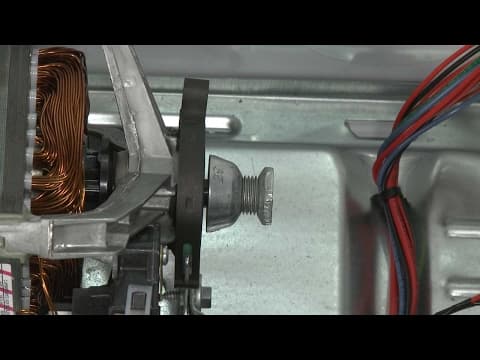
Now reach under the drum and push the idler pulley to release the tension on the belt then unthread the belt from the pulley and motor shaft.
25
You can use the belt to help lift out the drum.
26
Now unthread the screw securing the outlet vent to the blower housing.
27
Slide the vent out.
28
Depress the tabs to detach the plastic vent ring.
29
If you need the venting to exhaust out the left or right side of the cabinet, use a hammer and chisel to break the retaining tabs securing the appropriate rear knock-out cover.
30
Fully detach the cover. If you need to exhaust the vent through the base of the dryer, you will need to first set the dryer on its side before removing the bottom knock-out cover.
31
Next, attach the medium-sized vent piece from the kit to the blower housing.
32
Secure the vent with the screw. If exhausting through the dryer base, you will need to add the small extension vent piece in order to align the elbow section with the hole.
33
Insert the elbow section into the long vent and secure with a four-inch clamp.
34
Place another four-inch clamp over the end of the elbow section.
35
Insert the long vent through the hole in the cabinet or base and align the elbow on the vent piece attached to the blower outlet.
36
Tighten the clamp to secure. Be aware you will need to have at least ten inches of space between the wall and the cabinet when installing side venting.
37
Next, slide the plastic ring over the long vent piece and snap it into place in the hole.
38
Cover the old rear exhaust hole by positioning the tab of the provided metal cover plate in the opening from the inside.
39
Push down on the tab from behind the dryer to raise the plate.
40
Insert a small Phillips-head screwdriver through the larger hole to hold the plate in place as you use a number two Phillips-head screwdriver to thread the mounting screw to secure the plate.
41
If the venting has been changed from one side of the cabinet to the other, you can snap the provided plastic plug into the panel to fill the hole.
42
Replace the drum by aligning the smaller rim on the rear rollers.
43
Loop the belt around the pulley and motor shaft in a zig-zag formation.
44
Now, rotate the drum to help align the belt.
45
Reinstall the front bulkhead by hooking it onto the frame as you align the rollers under the drum.
46
Rethread and tighten the four screws to secure the bulkhead.
47
Reposition the lower retaining bracket and secure it with the screw.
48
Reconnect the moisture sensor wire harness.
49
Reposition the control housing bracket on the frame under the control board bracket.
50
Replace the screws to secure.
51
Reposition the front panel on the loosened screws
52
Feed the wire under the control housing bracket
53
Then align the top edge of the panel on the mounting tabs.
54
Thread and tighten the top screws.
55
Replace the screws behind the door.
56
Support the dryer
57
Tighten the two middle screws securing the bottom of the front panel.
58
Thread and tighten the outer screws.
59
Remove the support.
60
Connect the door switch wire harness.
61
Feed the control panel wire through the housing and control board mounting brackets and snap the control housing into place.
62
Thread the screws to secure.
63
Connect the wire connecter to the control board.
64
Realign the top panel and bracket then slide into position.
65
Rethread the rear screws and tighten.
66
With the reassembly complete, plug the power cord in
67
Attach and secure the exterior venting.
Description
This video provides step-by-step repair instructions for installing the vent kit on a Whirlpool electric dryer (model #WED85HEFW0). The vent kit can be used to to route the dryer exhaust vent in a different orientation.
This vent kit installation video is applicable to the following brands:
Whirlpool, Maytag
Tools needed: T-25 Torx bit, Phillips-head screwdriver, 1/4" socket
Don't forget to like and comment on this video and subscribe to our channel!
This vent kit installation video is applicable to the following brands:
Whirlpool, Maytag
Tools needed: T-25 Torx bit, Phillips-head screwdriver, 1/4" socket
Don't forget to like and comment on this video and subscribe to our channel!
Step-By-Step Instructions
1
Before you install the vent kit components in your dryer be sure to unplug the power cord.
2
The venting is detached from the dryer exhaust outlet.
3
Use a quarter-inch socket or nut driver to unthread the rear screws securing the top panel and bracket to the rear panel.
4
Slide the top panel back and lift up to detach.
5
Next, unthread the screws securing the control housing.
6
Disconnect the control panel wire connecter from the control board.
7
You can now lift the control housing and panel up and out to remove.
8
Disconnect the door switch wire harness.
9
Lift up the front of the dryer and support it.
10
Use the quarter-inch socket or nut driver to fully unthread the outer screws securing the bottom of the front panel.
11
Loosen the two middle screws.
12
Remove the support and lower the appliance.
13
Now open the dryer door and use a Phillips-head screwdriver to unthread the two screws securing the front panel to the bulkhead.
14
Use the quarter-inch socket or nut driver to unthread the three top screws.
15
Now lift the front panel up and out to remove.
16
Next, unthread the screws securing the control housing bracket.
17
Unthread the screw securing the front of the control board bracket.
18
Use wire or tape to support the bracket.
19
You can now lift the control housing bracket up to remove.
20
Disconnect the moisture sensor wire harness.
21
Unthread the screw to release the lower retaining bracket.
22
Now unthread the four screws securing the front bulkhead to the frame.
23
Lift the bulkhead up and detach it from the drum and frame.
24
Now reach under the drum and push the idler pulley to release the tension on the belt then unthread the belt from the pulley and motor shaft.
25
You can use the belt to help lift out the drum.
26
Now unthread the screw securing the outlet vent to the blower housing.
27
Slide the vent out.
28
Depress the tabs to detach the plastic vent ring.
29
If you need the venting to exhaust out the left or right side of the cabinet, use a hammer and chisel to break the retaining tabs securing the appropriate rear knock-out cover.
30
Fully detach the cover. If you need to exhaust the vent through the base of the dryer, you will need to first set the dryer on its side before removing the bottom knock-out cover.
31
Next, attach the medium-sized vent piece from the kit to the blower housing.
32
Secure the vent with the screw. If exhausting through the dryer base, you will need to add the small extension vent piece in order to align the elbow section with the hole.
33
Insert the elbow section into the long vent and secure with a four-inch clamp.
34
Place another four-inch clamp over the end of the elbow section.
35
Insert the long vent through the hole in the cabinet or base and align the elbow on the vent piece attached to the blower outlet.
36
Tighten the clamp to secure. Be aware you will need to have at least ten inches of space between the wall and the cabinet when installing side venting.
37
Next, slide the plastic ring over the long vent piece and snap it into place in the hole.
38
Cover the old rear exhaust hole by positioning the tab of the provided metal cover plate in the opening from the inside.
39
Push down on the tab from behind the dryer to raise the plate.
40
Insert a small Phillips-head screwdriver through the larger hole to hold the plate in place as you use a number two Phillips-head screwdriver to thread the mounting screw to secure the plate.
41
If the venting has been changed from one side of the cabinet to the other, you can snap the provided plastic plug into the panel to fill the hole.
42
Replace the drum by aligning the smaller rim on the rear rollers.
43
Loop the belt around the pulley and motor shaft in a zig-zag formation.
44
Now, rotate the drum to help align the belt.
45
Reinstall the front bulkhead by hooking it onto the frame as you align the rollers under the drum.
46
Rethread and tighten the four screws to secure the bulkhead.
47
Reposition the lower retaining bracket and secure it with the screw.
48
Reconnect the moisture sensor wire harness.
49
Reposition the control housing bracket on the frame under the control board bracket.
50
Replace the screws to secure.
51
Reposition the front panel on the loosened screws
52
Feed the wire under the control housing bracket
53
Then align the top edge of the panel on the mounting tabs.
54
Thread and tighten the top screws.
55
Replace the screws behind the door.
56
Support the dryer
57
Tighten the two middle screws securing the bottom of the front panel.
58
Thread and tighten the outer screws.
59
Remove the support.
60
Connect the door switch wire harness.
61
Feed the control panel wire through the housing and control board mounting brackets and snap the control housing into place.
62
Thread the screws to secure.
63
Connect the wire connecter to the control board.
64
Realign the top panel and bracket then slide into position.
65
Rethread the rear screws and tighten.
66
With the reassembly complete, plug the power cord in
67
Attach and secure the exterior venting.
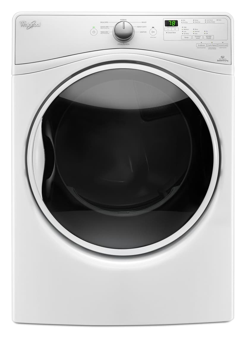
Applicable Product Model
Parts Needed
Side Venting Kit
$70.94
Total$0.00
Related Articles & Videos
10:42
Part Replacement
Whirlpool Alpha Electric Dryer Heating Element Replacement #WP8544771
09:26
Part Replacement
Whirlpool Alpha Electric Dryer Motor Pulley Replacement #WP8066184
00:47
Part Replacement
Whirlpool Alpha Electric Dryer Drying Rack Installation #W10886894




Our Story
Family-owned and operated since 1912, Burke America Parts Group is the longest-running genuine appliance, HVAC, and outdoor power equipment parts solution in North America. At Repair Clinic, we're proud to be an international brand trusted by the pros as well as the DIY community.
About Repair Clinic
© 2026 RepairClinic.com