

Price Match Guarantee

In-stock parts ship the same day

365-Day Return Policy
Price Match GuaranteeGET PRO PRICING
Video & Articles: Appliance & Equipment RepairKitchenAid Convection Gas Range Left Front Burner Valve Replacement #W11109973 


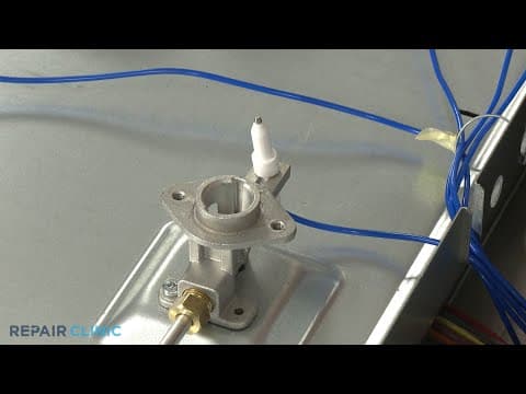
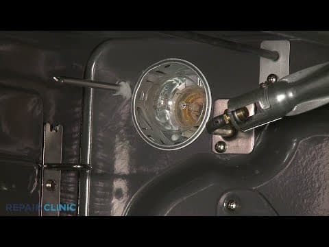
KitchenAid Convection Gas Range Left Front Burner Valve Replacement #W11109973
Skill Level
Total Parts Cost
$177.30Estimated Savings
$112.5006:47
- Description
This video provides step-by-step repair instructions for replacing the left front burner valve on a Kitchenaid Gas Convection Range (model #KSGB900ESS01). The most common reason for replacing the valve is if the gas is not reaching the burner, causing it to not light.
This valve replacement video is applicable to the following brands:
Whirlpool, Kitchenaid
Don't forget to like and comment on this video and subscribe to our channel!
This valve replacement video is applicable to the following brands:
Whirlpool, Kitchenaid
Don't forget to like and comment on this video and subscribe to our channel!
Step By Step Instructions
1
Convection Gas Range - Ksgb900ess1
2
Kitchenaid Convection Gas Range - Left Front Burner Base Replacement
3
You Will Need A 1/8th Inch Non-flared Flat-head Screwdriver, Half-inch Wrench, 9/16th Wrench, And A Phillips-head Screwdriver To Complete This Repair.
4
Shock
5
Unplug The Power Cord Or Shut Off The Power Supply.
6
Fire
7
Shut Off The Gas Supply As Well.
8
Open The Oven Door.
9
Use A Phillips-head Screwdriver To Unthread The Screws Securing The Control Panel?s Lower Cover.
10
Sharp
11
Remove The Cover.
12
Pull Off The Five Control Knobs.
13
Next, Unthread The Two Screws Securing The Control Panel To The Frame.
14
Detach The Control Panel, Then Disconnect The Display Board Wire Connecter And The Touch-pad Ribbon Connecter To Fully Release The Panel.
15
Use A 9/16th Inch Wrench To Unthread The Nut Securing The Main Gas Supply Tube To The Burner Valve.
16
Use A Half-inch Wrench To Unthread The Nut To Release The Simmer Gas Supply Tube From The Valve.
17
To Access Both Valve Clamping Bracket Screws, You?ll Need To Partially Uninstall The Manifold.
18
To Do This, Use The Half-inch Wrench To Unthread The Remaining Gas Supply Tubes From The Burner Valves.
19
Use An Adjustable Wrench To Help Unthread The Nut Securing The Main Gas Supply Line To The Manifold.
20
Now Unthread The Two Mounting Screws To Release The Manifold And Move It Out Of The Way.
21
Slide Off The Gasket And Spark Switch From The Left Front Burner Valve.
22
Unthread The Two Screws To Detach The Clamping Bracket And You Can Remove The Old Burner Valve.
23
Install The New Surface Burner Valve, By Aligning It On The Manifold?then Position The Clamping Bracket, And Thread The Screws To Secure.
24
Align The Spark Switch And Snap It Into Place On The Valve.
25
Slide The Gasket Onto The Valve Stem.
26
Realign The Manifold On The Front Brackets So The Valves Align With The Gas Supply Tubes Then Secure The Manifold With The Mounting Screws.
27
Reconnect The Main Gas Supply Line To The Manifold And Thread The Nut To Secure ? Be Careful Not To Damage The Line By Overtightening The Nut.
28
Connect The Rest Of The Gas Supply Tubes To The Appropriate Valves ? Again, Avoid Overtightening The Nuts.
29
Reinstall The Control Panel By First Connecting The Wire Connecter To The Display Board, And The Ribbon Connecter To The Touch-pad.
30
Realign The Control Panel On The Front Brackets.
31
Secure It With The Screws.
32
Replace The Lower Cover, Then Thread The Screws To Secure.
33
Realign The Control Knobs On The Valve Stems And Push Them Into Place ? Note That The Power Burner Control Knob Should Be Placed On The Second Stem From The Left.
34
Turn The Gas Supply Back On, And Plug The Power Cord Back In Or Restore The Power Supply.
35
It?s A Good Idea To Make Sure The Flame Height Is Properly Adjusted After Installing A New Burner Valve.
36
You Can Do This On Any Of The Valves By Setting The Burner To ?low", Then Remove The Control Knob And Secure The Burner Valve Stem With A Pair Of Pliers.
37
Using A 1/8th Inch Non-flared Flat-head Screwdriver, Rotate The Adjustment Screw Inside The Stem Clockwise, To Decrease The Flame Height, And Counter-clockwise To Increase The Height Of The Flame.
Description
This video provides step-by-step repair instructions for replacing the left front burner valve on a Kitchenaid Gas Convection Range (model #KSGB900ESS01). The most common reason for replacing the valve is if the gas is not reaching the burner, causing it to not light.
This valve replacement video is applicable to the following brands:
Whirlpool, Kitchenaid
Don't forget to like and comment on this video and subscribe to our channel!
This valve replacement video is applicable to the following brands:
Whirlpool, Kitchenaid
Don't forget to like and comment on this video and subscribe to our channel!
Step-By-Step Instructions
1
Convection Gas Range - Ksgb900ess1
2
Kitchenaid Convection Gas Range - Left Front Burner Base Replacement
3
You Will Need A 1/8th Inch Non-flared Flat-head Screwdriver, Half-inch Wrench, 9/16th Wrench, And A Phillips-head Screwdriver To Complete This Repair.
4
Shock
5
Unplug The Power Cord Or Shut Off The Power Supply.
6
Fire
7
Shut Off The Gas Supply As Well.
8
Open The Oven Door.
9
Use A Phillips-head Screwdriver To Unthread The Screws Securing The Control Panel?s Lower Cover.
10
Sharp
11
Remove The Cover.
12
Pull Off The Five Control Knobs.
13
Next, Unthread The Two Screws Securing The Control Panel To The Frame.
14
Detach The Control Panel, Then Disconnect The Display Board Wire Connecter And The Touch-pad Ribbon Connecter To Fully Release The Panel.
15
Use A 9/16th Inch Wrench To Unthread The Nut Securing The Main Gas Supply Tube To The Burner Valve.
16
Use A Half-inch Wrench To Unthread The Nut To Release The Simmer Gas Supply Tube From The Valve.
17
To Access Both Valve Clamping Bracket Screws, You?ll Need To Partially Uninstall The Manifold.
18
To Do This, Use The Half-inch Wrench To Unthread The Remaining Gas Supply Tubes From The Burner Valves.
19
Use An Adjustable Wrench To Help Unthread The Nut Securing The Main Gas Supply Line To The Manifold.
20
Now Unthread The Two Mounting Screws To Release The Manifold And Move It Out Of The Way.
21
Slide Off The Gasket And Spark Switch From The Left Front Burner Valve.
22
Unthread The Two Screws To Detach The Clamping Bracket And You Can Remove The Old Burner Valve.
23
Install The New Surface Burner Valve, By Aligning It On The Manifold?then Position The Clamping Bracket, And Thread The Screws To Secure.
24
Align The Spark Switch And Snap It Into Place On The Valve.
25
Slide The Gasket Onto The Valve Stem.
26
Realign The Manifold On The Front Brackets So The Valves Align With The Gas Supply Tubes Then Secure The Manifold With The Mounting Screws.
27
Reconnect The Main Gas Supply Line To The Manifold And Thread The Nut To Secure ? Be Careful Not To Damage The Line By Overtightening The Nut.
28
Connect The Rest Of The Gas Supply Tubes To The Appropriate Valves ? Again, Avoid Overtightening The Nuts.
29
Reinstall The Control Panel By First Connecting The Wire Connecter To The Display Board, And The Ribbon Connecter To The Touch-pad.
30
Realign The Control Panel On The Front Brackets.
31
Secure It With The Screws.
32
Replace The Lower Cover, Then Thread The Screws To Secure.
33
Realign The Control Knobs On The Valve Stems And Push Them Into Place ? Note That The Power Burner Control Knob Should Be Placed On The Second Stem From The Left.
34
Turn The Gas Supply Back On, And Plug The Power Cord Back In Or Restore The Power Supply.
35
It?s A Good Idea To Make Sure The Flame Height Is Properly Adjusted After Installing A New Burner Valve.
36
You Can Do This On Any Of The Valves By Setting The Burner To ?low", Then Remove The Control Knob And Secure The Burner Valve Stem With A Pair Of Pliers.
37
Using A 1/8th Inch Non-flared Flat-head Screwdriver, Rotate The Adjustment Screw Inside The Stem Clockwise, To Decrease The Flame Height, And Counter-clockwise To Increase The Height Of The Flame.
Applicable Product Model
Parts Needed
Surface Burner Valve
$177.30
Recommended Tools and Accessories
Cooktop Cleaner
$29.50
Total$0.00
Related Articles & Videos
09:43
Part Replacement
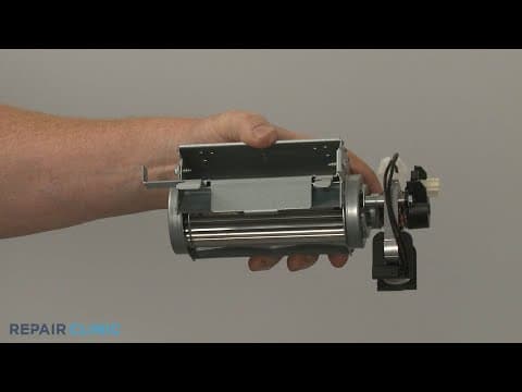
KitchenAid Convection Gas Range Cooling Fan Assembly Replacement #W11107275
08:32
Part Replacement
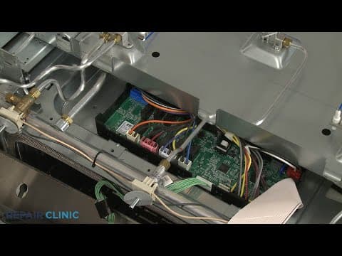
KitchenAid Convection Gas Range Main Control Board Replacement #W11100100
05:52
Part Replacement
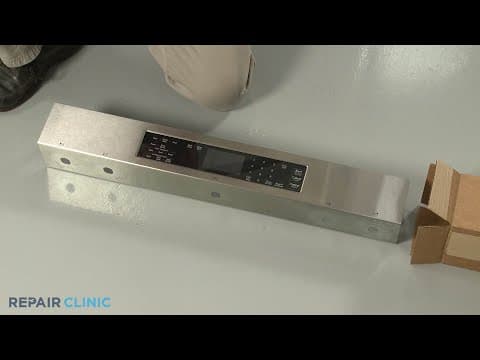
KitchenAid Convection Gas Range Control Panel Replacement #W10913685
07:53
Part Replacement
KitchenAid Convection Gas Range Right Rear Burner Spark Electrode Replacement #W11220383




Our Story
Family-owned and operated since 1912, Burke America Parts Group is the longest-running genuine appliance, HVAC, and outdoor power equipment parts solution in North America. At Repair Clinic, we're proud to be an international brand trusted by the pros as well as the DIY community.
About Repair Clinic
© 2026 RepairClinic.com