

Price Match Guarantee

In-stock parts ship the same day

365-Day Return Policy
Price Match GuaranteeGET PRO PRICING
Video & Articles: Appliance & Equipment RepairFrigidaire Range Vent Hood Blower Assembly Replacement 5304482255 
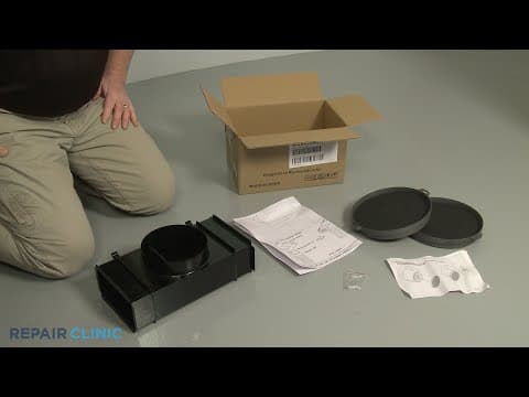
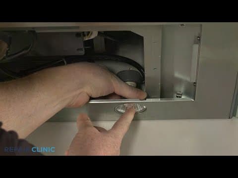
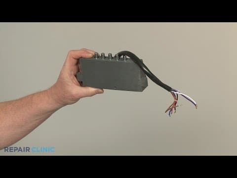
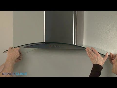
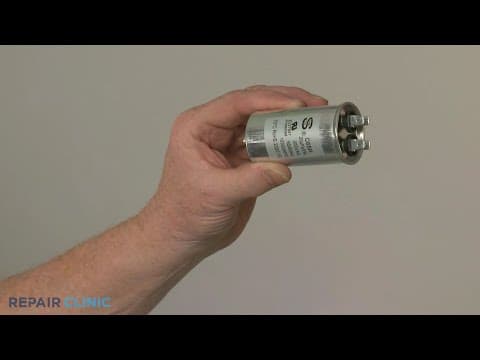
Frigidaire Range Vent Hood Blower Assembly Replacement 5304482255
Skill Level
Total Parts Cost
$313.95Estimated Savings
$112.5017:57
- Description
This video provides step-by-step repair instructions for replacing the blower assembly on a Frigidaire Range Vent Hood (model FHWC3660LSA). The most common reason for replacing this part is if it is not venting air at all.
All of the information for this part replacement video is applicable to the following brands:
Frigidaire
All of the information for this part replacement video is applicable to the following brands:
Frigidaire
Step By Step Instructions
1
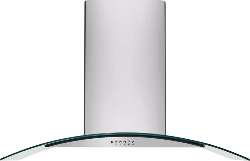
Frigidaire Range Vent Hood - FHWC3660LSA
2
Frigidaire Range Vent Hood Blower Assembly Replacement
3
Tools needed: Phillips-head screwdriver, small flat-head screwdriver, 2.5mm Allen wrench, 7mm nut driver, 9/32nd inch nut driver
4
Shock
5
Before you begin, be sure to turn off the power supply to the hood.
6
Use the Phillips-head screwdriver to unthread the left and right side screws securing the upper chimney to the upper mounting bracket.
7
Heavy
8
Slide the chimney down into the lower chimney then have an assistant help to lift both sections up to detach them from the lower mounting bracket.
9
Detach the venting from the damper.
10
Unthread the two screws securing the junction box cover.
11
Remove the cover and note the orientation of the power and grounding wires.
12
Untwist the wire nuts to separate the power wires.
13
Use the 7mm nut driver to unthread the nut to release the grounding wire.
14
Pull the wires out of the junction box.
15
Unthread the four mounting screws securing the canopy glass using the 2.5mm Allen wrench.
16
With the screws unthreaded, have an assistant help you to remove the glass.
17
Pull the right-side lever down to release the grease filter.
18
Sharp
19
Unthread the two lower mounting screws securing the appliance to the wall.
20
Next, loosen the two upper mounting screws.
21
Heavy
22
With the screws loosened, you can lift the vent hood up and out to remove.
23
With the front of the hood facing down, set it on a towel or blanket.
24
Now unthread the two rear outside screws securing the stainless-steel panel to the cabinet.
25
Next, use the 9/32nd inch nut driver and Phillips-head screwdriver to unthread the two sets of nuts and bolts in the middle.
26
Now unthread the eight screws securing the panel to the base of the appliance.
27
Rotate the two light bulbs counter-clockwise to remove them from their holders.
28
Sharp
29
You can now detach the panel.
30
Unthread the screws to release the selector switch assembly so you can set the panel aside.
31
Now rotate the two lamp holder assemblies to release them from the cabinet.
32
Unthread the two left-side screws securing the blower assembly.
33
Unthread the two right-side screws as well.
34
Next, unthread the two screws securing the blower assembly bracket to the rear mounting plate.
35
Use the 7mm nut driver to unthread the nut to release the blower assembly grounding wire.
36
Using the Phillips-head screwdriver, unthread the four screws to release the terminal block cover.
37
Pull the terminal blocks out.
38
Shock
39
Release the potentially-stored electrical charge in the capacitor to avoid injury.
40
You can do this by placing a screwdriver blade across the terminals.
41
Loosen the screw securing the capacitor retaining plate to release the component.
42
Now unthread the two screws to release the terminal block housing from the cabinet.
43
Cut the zip-ties securing the blower assembly wires.
44
Disconnect the wires from the capacitor.
45
Now note the orientation of the blower assembly wires connected to the terminal blocks, then use the small flat-head screwdriver to loosen the screws to release the wires.
46
You can now remove the old blower assembly.
47
To install the new blower assembly, position it in the cabinet.
48
Insert the wires into the appropriate terminals on the terminal blocks and tighten the screws to secure.
49
Connect the wires to the capacitor terminals as well.
50
Use new zip-ties to secure the wires.
51
Align the terminal block housing on the new blower assembly and thread the screws to secure.
52
Reposition the capacitor by inserting the mounting post behind the retaining plate, then tighten the screw to fully secure the plate.
53
Reposition the terminal blocks then align the cover.
54
Thread the screws to secure the cover.
55
Align the blower assembly grounding wire on the cabinet post, slide on the washer, then thread the nut to secure.
56
Fully position the blower assembly and thread the two screws to secure the assembly bracket to the rear mounting plate.
57
Thread the two left-side screws.
58
Thread the two right-side screws as well.
59
Align the two lamp holder assemblies with the holes in the cabinet and rotate both to lock them into place.
60
Realign the selector switch assembly in the stainless-steel panel and secure it with the screws.
61
Reposition the panel and rethread the eight inner mounting screws.
62
Thread the two sets of nuts and bolts in the middle to secure the panel to the cabinet.
63
Rethread the two outside screws as well.
64
Replace the two light bulbs by inserting the terminals into the holders then rotate clockwise.
65
Reinstall the range vent hood by aliging the rear slots over the upper mounting screws threaded into the wall.
66
Partially tighten the screws to maintain an even gap between the wall and cabinet.
67
Rethread the lower mounting screws.
68
Reinstall the grease filter by aligning the left side tabs with the slots in the hood, then pull the lever to align the right side.
69
Before you reinstall the canopy glass, confirm the hood gasket is intact and aligned.
70
Reposition the glass.
71
Thread the four screws to secure.
72
Fragile
73
Avoid over-tightening the screws.
74
Feed the power and grounding wires through the hole in the junction box.
75
Secure the grounding wires with the nut.
76
Join the black wires and use the wire nut to twist the wires together.
77
Do the same to join the white wires together.
78
Replace the junction box cover and secure it with the screws.
79
Attach the venting to the damper.
80
Slide the upper chimney section into the lower chimney section.
81
Now align the bottom edge of the lower chimney in the groove between the canopy glass and blower housing cabinet.
82
Hook the lower chimney slots on the lower mounting bracket tabs.
83
Lift the upper chimney section up so its flush with the ceiling, then thread the screws to secure the chimney to the upper mounting bracket.
84
Turn the power supply back on and the range vent hood should be ready for use.
Description
This video provides step-by-step repair instructions for replacing the blower assembly on a Frigidaire Range Vent Hood (model FHWC3660LSA). The most common reason for replacing this part is if it is not venting air at all.
All of the information for this part replacement video is applicable to the following brands:
Frigidaire
All of the information for this part replacement video is applicable to the following brands:
Frigidaire
Step-By-Step Instructions
1
Frigidaire Range Vent Hood - FHWC3660LSA
2
Frigidaire Range Vent Hood Blower Assembly Replacement
3
Tools needed: Phillips-head screwdriver, small flat-head screwdriver, 2.5mm Allen wrench, 7mm nut driver, 9/32nd inch nut driver
4
Shock
5
Before you begin, be sure to turn off the power supply to the hood.
6
Use the Phillips-head screwdriver to unthread the left and right side screws securing the upper chimney to the upper mounting bracket.
7
Heavy
8
Slide the chimney down into the lower chimney then have an assistant help to lift both sections up to detach them from the lower mounting bracket.
9
Detach the venting from the damper.
10
Unthread the two screws securing the junction box cover.
11
Remove the cover and note the orientation of the power and grounding wires.
12
Untwist the wire nuts to separate the power wires.
13
Use the 7mm nut driver to unthread the nut to release the grounding wire.
14
Pull the wires out of the junction box.
15
Unthread the four mounting screws securing the canopy glass using the 2.5mm Allen wrench.
16
With the screws unthreaded, have an assistant help you to remove the glass.
17
Pull the right-side lever down to release the grease filter.
18
Sharp
19
Unthread the two lower mounting screws securing the appliance to the wall.
20
Next, loosen the two upper mounting screws.
21
Heavy
22
With the screws loosened, you can lift the vent hood up and out to remove.
23
With the front of the hood facing down, set it on a towel or blanket.
24
Now unthread the two rear outside screws securing the stainless-steel panel to the cabinet.
25
Next, use the 9/32nd inch nut driver and Phillips-head screwdriver to unthread the two sets of nuts and bolts in the middle.
26
Now unthread the eight screws securing the panel to the base of the appliance.
27
Rotate the two light bulbs counter-clockwise to remove them from their holders.
28
Sharp
29
You can now detach the panel.
30
Unthread the screws to release the selector switch assembly so you can set the panel aside.
31
Now rotate the two lamp holder assemblies to release them from the cabinet.
32
Unthread the two left-side screws securing the blower assembly.
33
Unthread the two right-side screws as well.
34
Next, unthread the two screws securing the blower assembly bracket to the rear mounting plate.
35
Use the 7mm nut driver to unthread the nut to release the blower assembly grounding wire.
36
Using the Phillips-head screwdriver, unthread the four screws to release the terminal block cover.
37
Pull the terminal blocks out.
38
Shock
39
Release the potentially-stored electrical charge in the capacitor to avoid injury.
40
You can do this by placing a screwdriver blade across the terminals.
41
Loosen the screw securing the capacitor retaining plate to release the component.
42
Now unthread the two screws to release the terminal block housing from the cabinet.
43
Cut the zip-ties securing the blower assembly wires.
44
Disconnect the wires from the capacitor.
45
Now note the orientation of the blower assembly wires connected to the terminal blocks, then use the small flat-head screwdriver to loosen the screws to release the wires.
46
You can now remove the old blower assembly.
47
To install the new blower assembly, position it in the cabinet.
48
Insert the wires into the appropriate terminals on the terminal blocks and tighten the screws to secure.
49
Connect the wires to the capacitor terminals as well.
50
Use new zip-ties to secure the wires.
51
Align the terminal block housing on the new blower assembly and thread the screws to secure.
52
Reposition the capacitor by inserting the mounting post behind the retaining plate, then tighten the screw to fully secure the plate.
53
Reposition the terminal blocks then align the cover.
54
Thread the screws to secure the cover.
55
Align the blower assembly grounding wire on the cabinet post, slide on the washer, then thread the nut to secure.
56
Fully position the blower assembly and thread the two screws to secure the assembly bracket to the rear mounting plate.
57
Thread the two left-side screws.
58
Thread the two right-side screws as well.
59
Align the two lamp holder assemblies with the holes in the cabinet and rotate both to lock them into place.
60
Realign the selector switch assembly in the stainless-steel panel and secure it with the screws.
61
Reposition the panel and rethread the eight inner mounting screws.
62
Thread the two sets of nuts and bolts in the middle to secure the panel to the cabinet.
63
Rethread the two outside screws as well.
64
Replace the two light bulbs by inserting the terminals into the holders then rotate clockwise.
65
Reinstall the range vent hood by aliging the rear slots over the upper mounting screws threaded into the wall.
66
Partially tighten the screws to maintain an even gap between the wall and cabinet.
67
Rethread the lower mounting screws.
68
Reinstall the grease filter by aligning the left side tabs with the slots in the hood, then pull the lever to align the right side.
69
Before you reinstall the canopy glass, confirm the hood gasket is intact and aligned.
70
Reposition the glass.
71
Thread the four screws to secure.
72
Fragile
73
Avoid over-tightening the screws.
74
Feed the power and grounding wires through the hole in the junction box.
75
Secure the grounding wires with the nut.
76
Join the black wires and use the wire nut to twist the wires together.
77
Do the same to join the white wires together.
78
Replace the junction box cover and secure it with the screws.
79
Attach the venting to the damper.
80
Slide the upper chimney section into the lower chimney section.
81
Now align the bottom edge of the lower chimney in the groove between the canopy glass and blower housing cabinet.
82
Hook the lower chimney slots on the lower mounting bracket tabs.
83
Lift the upper chimney section up so its flush with the ceiling, then thread the screws to secure the chimney to the upper mounting bracket.
84
Turn the power supply back on and the range vent hood should be ready for use.
Applicable Product Model
Related Articles & Videos
05:29
Part Replacement
Frigidaire Range Vent Hood Recirculation Kit Installation 5304482271
04:51
Part Replacement
Frigidaire Range Vent Hood Selector Switch Assembly Replacement 5304482236




Our Story
Family-owned and operated since 1912, Burke America Parts Group is the longest-running genuine appliance, HVAC, and outdoor power equipment parts solution in North America. At Repair Clinic, we're proud to be an international brand trusted by the pros as well as the DIY community.
About Repair Clinic
© 2026 RepairClinic.com