

Price Match Guarantee

In-stock parts ship the same day

365-Day Return Policy
Price Match GuaranteeGET PRO PRICING
Video & Articles: Appliance & Equipment RepairCarrier/Gree ETAC Heat Pump Solenoid Coil Replacement 4300040022 

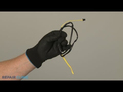
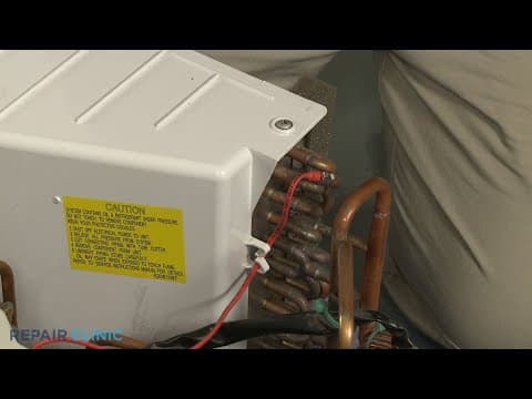
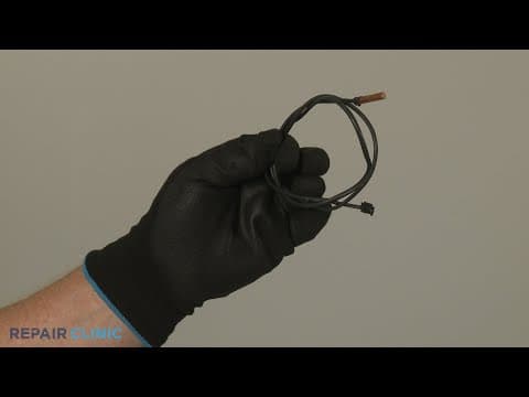
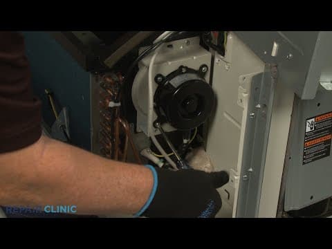
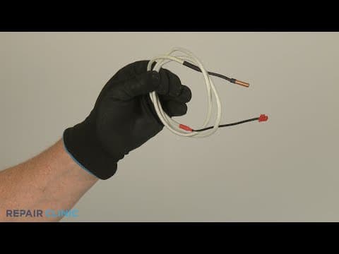
Carrier/Gree ETAC Heat Pump Solenoid Coil Replacement 4300040022
Skill Level
Total Parts Cost
$22.36Estimated Savings
$112.5010:24
- Description
This video provides step-by-step instructions for replacing the solenoid coil on a Carrier/Gree ETAC Heat Pump Unit. The most common reason for replacing this part is if the unit is not cooling or heating properly.
All of the information in this video is applicable to the following brands: Carrier, Gree
All of the information in this video is applicable to the following brands: Carrier, Gree
Step By Step Instructions
1
To replace the refrigerant solenoid coil in this carrier/gree etac heat pump unit…
2
… you will need a #2 phillips-head screwdriver, needle-nose pliers, wire cutters, zip-ties, and a power drill with a 5/16th inch socket.
3
Before you begin, be sure to turn the unit off…
4
…and disconnect the power supply.
5
When performing this procedure, you will need to fully uninstall the unit from the wall.
6
To do this…
7
… remove the unit’s front panel by pulling the bottom of the panel out to release it from the tabs…then lift up.
8
If applicable, disconnect the wall thermostat wire connecter and the energy management wire connecter.
9
Using the power drill with the 5/16th inch socket, unthread the four mounting screws securing the unit to the wall sleeve.
10
Now have an assistant help you to slide the unit out of the sleeve…
11
… and set it on a towel or blanket.
12
Use the #2 phillips-head screwdriver to unthread the screw securing the control panel.
13
Detach the control panel.
14
Now unthread the lower right screw securing the junction box cover.
15
Unthread the three screws securing the junction box itself.
16
Pull back the cover to fully detach the junction box from the power cord.
17
Disconnect the power cord wire connecter.
18
Next, unthread the six screws securing the control box’s side access cover.
19
Remove the cover.
20
Unthread the four screws to release the left access cover.
21
Now unthread the five screws securing the middle access cover.
22
Disconnect the relay board and transformer wire connecters from the main control board to move the cover out of the way.
23
Use the wire cutters to cut the zip-tie bundling the control box wires together.
24
Use the needle-nose pliers to pull back the insulators covering the two purple wires connected to the relay and power control board… then depress the retaining tabs to disconnect the wires.
25
Pull the wires through the hole in the side of the control box.
26
Next, unthread the screw so you can detach the wire cover.
27
Cut the zip-tie securing the solenoid wires.
28
Now unthread the screw securing the solenoid.
29
With the screw unthreaded, you can slide the old solenoid off the reversing valve and fully remove the old component.
30
To install the new refrigerant solenoid coil…
31
… slide it onto the reversing valve…
32
… and thread the screw to secure.
33
Secure the wiring in the retainer…
34
… then use a new zip-tie to secure the wiring sleeve to the other wires.
35
Feed the wires through the access hole in the frame…
36
… and through the hole in the side of the control box.
37
Replace the wire cover and thread the screw to secure.
38
Connect the wires to the relay and power control board and slide the insulators over the terminals.
39
Use a new zip-tie to bundle the control box wires together.
40
Reconnect the relay board and transformer wire connecters to the main control board…
41
… then realign the middle access cover and thread the five screws.
42
Reposition the left access cover…
43
… and rethread the screws.
44
Realign the side access cover…
45
… and thread the screws to secure.
46
Reconnect the power cord wire connecter…
47
… then reposition the junction box and rethread the screws.
48
Rethread the lower right screw to fully secure the cover.
49
Realign the control panel and thread the screw to secure.
50
Reinstall the unit by sliding it into the wall sleeve until the seal rests against the front of the sleeve.
51
Rethread the mounting screws to secure the unit.
52
Avoid over-tightening the screws.
53
Reconnect the wall thermostat and energy management wire connecters if applicable.
54
Reinstall the front panel by aligning the tabs over the top rail then push the bottom of the panel in until it snaps into place.
55
Restore power to the unit…
56
… and the etac heat pump system should be ready for use.
Description
This video provides step-by-step instructions for replacing the solenoid coil on a Carrier/Gree ETAC Heat Pump Unit. The most common reason for replacing this part is if the unit is not cooling or heating properly.
All of the information in this video is applicable to the following brands: Carrier, Gree
All of the information in this video is applicable to the following brands: Carrier, Gree
Step-By-Step Instructions
1
To replace the refrigerant solenoid coil in this carrier/gree etac heat pump unit…
2
… you will need a #2 phillips-head screwdriver, needle-nose pliers, wire cutters, zip-ties, and a power drill with a 5/16th inch socket.
3
Before you begin, be sure to turn the unit off…
4
…and disconnect the power supply.
5
When performing this procedure, you will need to fully uninstall the unit from the wall.
6
To do this…
7
… remove the unit’s front panel by pulling the bottom of the panel out to release it from the tabs…then lift up.
8
If applicable, disconnect the wall thermostat wire connecter and the energy management wire connecter.
9
Using the power drill with the 5/16th inch socket, unthread the four mounting screws securing the unit to the wall sleeve.
10
Now have an assistant help you to slide the unit out of the sleeve…
11
… and set it on a towel or blanket.
12
Use the #2 phillips-head screwdriver to unthread the screw securing the control panel.
13
Detach the control panel.
14
Now unthread the lower right screw securing the junction box cover.
15
Unthread the three screws securing the junction box itself.
16
Pull back the cover to fully detach the junction box from the power cord.
17
Disconnect the power cord wire connecter.
18
Next, unthread the six screws securing the control box’s side access cover.
19
Remove the cover.
20
Unthread the four screws to release the left access cover.
21
Now unthread the five screws securing the middle access cover.
22
Disconnect the relay board and transformer wire connecters from the main control board to move the cover out of the way.
23
Use the wire cutters to cut the zip-tie bundling the control box wires together.
24
Use the needle-nose pliers to pull back the insulators covering the two purple wires connected to the relay and power control board… then depress the retaining tabs to disconnect the wires.
25
Pull the wires through the hole in the side of the control box.
26
Next, unthread the screw so you can detach the wire cover.
27
Cut the zip-tie securing the solenoid wires.
28
Now unthread the screw securing the solenoid.
29
With the screw unthreaded, you can slide the old solenoid off the reversing valve and fully remove the old component.
30
To install the new refrigerant solenoid coil…
31
… slide it onto the reversing valve…
32
… and thread the screw to secure.
33
Secure the wiring in the retainer…
34
… then use a new zip-tie to secure the wiring sleeve to the other wires.
35
Feed the wires through the access hole in the frame…
36
… and through the hole in the side of the control box.
37
Replace the wire cover and thread the screw to secure.
38
Connect the wires to the relay and power control board and slide the insulators over the terminals.
39
Use a new zip-tie to bundle the control box wires together.
40
Reconnect the relay board and transformer wire connecters to the main control board…
41
… then realign the middle access cover and thread the five screws.
42
Reposition the left access cover…
43
… and rethread the screws.
44
Realign the side access cover…
45
… and thread the screws to secure.
46
Reconnect the power cord wire connecter…
47
… then reposition the junction box and rethread the screws.
48
Rethread the lower right screw to fully secure the cover.
49
Realign the control panel and thread the screw to secure.
50
Reinstall the unit by sliding it into the wall sleeve until the seal rests against the front of the sleeve.
51
Rethread the mounting screws to secure the unit.
52
Avoid over-tightening the screws.
53
Reconnect the wall thermostat and energy management wire connecters if applicable.
54
Reinstall the front panel by aligning the tabs over the top rail then push the bottom of the panel in until it snaps into place.
55
Restore power to the unit…
56
… and the etac heat pump system should be ready for use.
Applicable Product Model
Related Articles & Videos
08:46
Part Replacement
Carrier/Gree ETAC Heat Pump Ambient Temperature Sensor Replacement 3900012123
10:01
Part Replacement
Carrier/Gree ETAC Heat Pump Outdoor Coil Temperature Sensor Replacement 390000372
08:31
Part Replacement
Carrier/Gree ETAC Heat Pump Indoor Coil Temperature Sensor Replacement 390000596
12:27
Part Replacement
Carrier/Gree ETAC Heat Pump Indoor Fan Motor Replacement 1501180211
11:30
Part Replacement
Carrier/Gree ETAC Heat Pump Discharge Air Temperature Sensor Replacement 390001982




Our Story
Family-owned and operated since 1912, Burke America Parts Group is the longest-running genuine appliance, HVAC, and outdoor power equipment parts solution in North America. At Repair Clinic, we're proud to be an international brand trusted by the pros as well as the DIY community.
About Repair Clinic
© 2026 RepairClinic.com