

Price Match Guarantee

In-stock parts ship the same day

365-Day Return Policy
Price Match GuaranteeGET PRO PRICING
Video & Articles: Appliance & Equipment RepairCub Cadet Snowblower Alternator Replacement #951-12050A

Cub Cadet Snowblower Alternator Replacement #951-12050A
Skill Level
Total Parts Cost
$58.51Estimated Savings
$112.5013:35
- Description
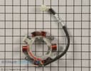
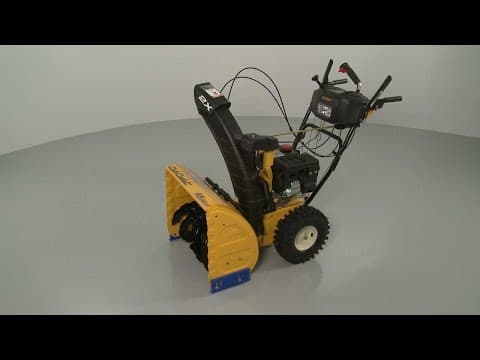
This video provides step-by-step repair instructions for replacing the alternator (or stator) on a Cub Cadet snowblower. The most common reason for replacing the alternator is when the snowblower battery keeps draining.
All of the information for this alternator replacement video is applicable to the following brands:
Cub Cadet, MTD, Troy-Bilt, Yard Machines, Yard-Man, Craftsman
Tools used: 3/8 inch socket, 1/2 inch socket, 3/4 inch socket, 10mm socket, Phillips-head screwdriver, pipe wrench, mallet, large flathead screwdriver, zip tie, business card
Step By Step Instructions
1
Before you replace the alternator on your snowblower first make sure the engine has cooled.
2
Next, remove the wire and boot from the spark plug to prevent the engine from accidentally starting.
3
We recommend performing this procedure with no fuel in the tank.
4
Your first step is to remove the retaining clip securing the chute control rod and pull the rod free.
5
Now remove the retaining clip securing the support bracket pin and pull out the pin.
6
Unthread the wing nut from the center gear box mounting bolt.
7
Lift the gear box off of the support bracket and set the gear box and chute assembly aside.
8
Next, use a 3/8th inch socket to remove the bolts securing the belt cover.
9
Pull the cover off.
10
Now release the drive belt idler pulley tension spring.
11
Use a half-inch socket to remove the upper two mounting bolts securing the gear box support bracket.
12
Use a three-quarter inch socket to remove the lower bolt.
13
You can now remove the support bracket.
14
Use a 10mm socket to remove all of the mounting bolts securing the muffler cover.
15
Lift off the cover.
16
Next, remove both the choke knob and the throttle knob.
17
Now use a phillips-head screwdriver to unthread the lower starter switch box mounting screw.
18
Detach the primer line and the ignition switch wires.
19
Use the 10mm socket to remove the nuts threaded on the carburetor mounting posts.
20
Pull the control panel free.
21
Release the retaining clamp securing the fuel line to the tank and pull the line off.
22
Remove the mounting bolts securing the tank.
23
Remove the dipstick and lift off the tank.
24
Use the 10mm socket to remove the bolts securing the blower housing.
25
Use a 5/16th socket to remove the bolt securing the spring guard to the housing and pull the housing off.
26
Now use a three-quarter inch socket and pipe wrench to help unthread the flywheel and starter cup mounting nut.
27
Pull off the starter cup and fan blade.
28
Tap the flywheel with a mallet to loosen.
29
Then use a large flathead screwdriver to help pry the flywheel off.
30
Use the 10mm socket to remove the mounting bolts to release the alternator.
31
Now loosen the bolt securing the guard plate and move the plate out of the way to release the alternator wire sleeve.
32
Cut the zip tie securing the alternator wires to the starter switch box cord.
33
Disconnect the wire harness to fully release the old alternator.
34
You’re now ready to install the new alternator.
35
Route the wire sleeve behind the guard plate, reposition the plate and tighten the bolt.
36
Now position the new alternator on the engine block and replace the mounting bolts to secure.
37
Connect the wire harness and use a zip tie to secure the wires to the switch box cord.
38
Confirm that the flywheel key is in place on the crankshaft and at the three o’clock position then realign the flywheel on the shaft.
39
Reposition the fan blade and the starter cup then thread and tighten the mounting nut to secure.
40
If necessary, you can realign the ignition coil by first rotating the flywheel magnets away from the coil.
41
Loosen the ignition coil mounting bolts.
42
Now pull the coil back and tighten the bolts.
43
Insert a business card between the coil and flywheel then rotate the flywheel so the magnets align with the coil.
44
Loosen the bolts to align the coil the correct distance from the flywheel.
45
Re-tighten the bolts and remove the card.
46
Reposition the blower housing.
47
Thread and tighten the bolts to secure.
48
Remember to secure the grounding wire under the lower bolt.
49
Reposition the fuel tank on the engine.
50
Thread and tighten the mounting bolts to secure the tank.
51
Remember to secure the starter switch box cord retainer with the bolt above the rear of the starter.
52
Replace the dipstick.
53
Reconnect the fuel line to the tank and secure it with the retaining clamp.
54
Reposition the control panel making sure the choke plate stem protrudes through the hole in the panel and the breather tube connects to the air intake box.
55
Thread the nuts on the mounting posts and tighten.
56
With the control panel in place, rethread the lower starter switch box mounting screw.
57
Reattach the primer line and the ignition switch wires.
58
Replace both the choke and the throttle knobs.
59
Reposition the fuel tank on the engine.
60
Connect the fuel line and secure it with the retaining clamp.
61
Thread and tighten the mounting bolts to secure the tank.
62
Remember to secure the starter switch box cord retainer with the bolt above the rear of the starter.
63
Realign the muffler cover.
64
Thread and tighten the bolts to secure.
65
Now reposition the chute gear box support bracket and replace the bolts.
66
Reset the tension spring on the lower bolt.
67
Replace the belt cover.
68
Rethread the bolts and tighten.
69
Position the chute assembly on the chute adapter. as you align the gear box on the support bracket.
70
Confirm that the center mounting bolt is in place in the gear box housing then thread the wing nut on and tighten.
71
Reinsert the support bracket pin and secure it with the retaining clip.
72
Confirm that the holes in the gear box coupler are facing straight up with the chute facing forward and that the chute control lever is at the “one o’clock” position.
73
Now insert the rounded end of the chute control rod into the gear box coupler and the hex end into the control coupler.
74
Secure the rod with the retaining clip.
75
Confirm that the chute has a full range of movement attach the spark plug wire and boot refill the fuel tank and your snowblower should be ready for use.
Description
This video provides step-by-step repair instructions for replacing the alternator (or stator) on a Cub Cadet snowblower. The most common reason for replacing the alternator is when the snowblower battery keeps draining.
All of the information for this alternator replacement video is applicable to the following brands:
Cub Cadet, MTD, Troy-Bilt, Yard Machines, Yard-Man, Craftsman
Tools used: 3/8 inch socket, 1/2 inch socket, 3/4 inch socket, 10mm socket, Phillips-head screwdriver, pipe wrench, mallet, large flathead screwdriver, zip tie, business card
All of the information for this alternator replacement video is applicable to the following brands:
Cub Cadet, MTD, Troy-Bilt, Yard Machines, Yard-Man, Craftsman
Tools used: 3/8 inch socket, 1/2 inch socket, 3/4 inch socket, 10mm socket, Phillips-head screwdriver, pipe wrench, mallet, large flathead screwdriver, zip tie, business card
Step-By-Step Instructions
1
Before you replace the alternator on your snowblower first make sure the engine has cooled.
2
Next, remove the wire and boot from the spark plug to prevent the engine from accidentally starting.
3
We recommend performing this procedure with no fuel in the tank.
4
Your first step is to remove the retaining clip securing the chute control rod and pull the rod free.
5
Now remove the retaining clip securing the support bracket pin and pull out the pin.
6
Unthread the wing nut from the center gear box mounting bolt.
7
Lift the gear box off of the support bracket and set the gear box and chute assembly aside.
8
Next, use a 3/8th inch socket to remove the bolts securing the belt cover.
9
Pull the cover off.
10
Now release the drive belt idler pulley tension spring.
11
Use a half-inch socket to remove the upper two mounting bolts securing the gear box support bracket.
12
Use a three-quarter inch socket to remove the lower bolt.
13
You can now remove the support bracket.
14
Use a 10mm socket to remove all of the mounting bolts securing the muffler cover.
15
Lift off the cover.
16
Next, remove both the choke knob and the throttle knob.
17
Now use a phillips-head screwdriver to unthread the lower starter switch box mounting screw.
18
Detach the primer line and the ignition switch wires.
19
Use the 10mm socket to remove the nuts threaded on the carburetor mounting posts.
20
Pull the control panel free.
21
Release the retaining clamp securing the fuel line to the tank and pull the line off.
22
Remove the mounting bolts securing the tank.
23
Remove the dipstick and lift off the tank.
24
Use the 10mm socket to remove the bolts securing the blower housing.
25
Use a 5/16th socket to remove the bolt securing the spring guard to the housing and pull the housing off.
26
Now use a three-quarter inch socket and pipe wrench to help unthread the flywheel and starter cup mounting nut.
27
Pull off the starter cup and fan blade.
28
Tap the flywheel with a mallet to loosen.
29
Then use a large flathead screwdriver to help pry the flywheel off.
30
Use the 10mm socket to remove the mounting bolts to release the alternator.
31
Now loosen the bolt securing the guard plate and move the plate out of the way to release the alternator wire sleeve.
32
Cut the zip tie securing the alternator wires to the starter switch box cord.
33
Disconnect the wire harness to fully release the old alternator.
34
You’re now ready to install the new alternator.
35
Route the wire sleeve behind the guard plate, reposition the plate and tighten the bolt.
36
Now position the new alternator on the engine block and replace the mounting bolts to secure.
37
Connect the wire harness and use a zip tie to secure the wires to the switch box cord.
38
Confirm that the flywheel key is in place on the crankshaft and at the three o’clock position then realign the flywheel on the shaft.
39
Reposition the fan blade and the starter cup then thread and tighten the mounting nut to secure.
40
If necessary, you can realign the ignition coil by first rotating the flywheel magnets away from the coil.
41
Loosen the ignition coil mounting bolts.
42
Now pull the coil back and tighten the bolts.
43
Insert a business card between the coil and flywheel then rotate the flywheel so the magnets align with the coil.
44
Loosen the bolts to align the coil the correct distance from the flywheel.
45
Re-tighten the bolts and remove the card.
46
Reposition the blower housing.
47
Thread and tighten the bolts to secure.
48
Remember to secure the grounding wire under the lower bolt.
49
Reposition the fuel tank on the engine.
50
Thread and tighten the mounting bolts to secure the tank.
51
Remember to secure the starter switch box cord retainer with the bolt above the rear of the starter.
52
Replace the dipstick.
53
Reconnect the fuel line to the tank and secure it with the retaining clamp.
54
Reposition the control panel making sure the choke plate stem protrudes through the hole in the panel and the breather tube connects to the air intake box.
55
Thread the nuts on the mounting posts and tighten.
56
With the control panel in place, rethread the lower starter switch box mounting screw.
57
Reattach the primer line and the ignition switch wires.
58
Replace both the choke and the throttle knobs.
59
Reposition the fuel tank on the engine.
60
Connect the fuel line and secure it with the retaining clamp.
61
Thread and tighten the mounting bolts to secure the tank.
62
Remember to secure the starter switch box cord retainer with the bolt above the rear of the starter.
63
Realign the muffler cover.
64
Thread and tighten the bolts to secure.
65
Now reposition the chute gear box support bracket and replace the bolts.
66
Reset the tension spring on the lower bolt.
67
Replace the belt cover.
68
Rethread the bolts and tighten.
69
Position the chute assembly on the chute adapter. as you align the gear box on the support bracket.
70
Confirm that the center mounting bolt is in place in the gear box housing then thread the wing nut on and tighten.
71
Reinsert the support bracket pin and secure it with the retaining clip.
72
Confirm that the holes in the gear box coupler are facing straight up with the chute facing forward and that the chute control lever is at the “one o’clock” position.
73
Now insert the rounded end of the chute control rod into the gear box coupler and the hex end into the control coupler.
74
Secure the rod with the retaining clip.
75
Confirm that the chute has a full range of movement attach the spark plug wire and boot refill the fuel tank and your snowblower should be ready for use.
Applicable Product Model
Parts Needed
Alternator
$58.51
Total$0.00
Related Articles & Videos




Our Story
Family-owned and operated since 1912, Burke America Parts Group is the longest-running genuine appliance, HVAC, and outdoor power equipment parts solution in North America. At Repair Clinic, we're proud to be an international brand trusted by the pros as well as the DIY community.
About Repair Clinic
© 2026 RepairClinic.com